
Microchip transfer system and method

A chip transfer, miniature technology, used in electronic circuit testing, measuring devices, instruments, etc., to achieve the effect of reducing volume, enhancing magnetism, and reducing the risk of errors

Active Publication Date: 2018-09-04
HUIZHOU THORLED OPTO
View PDF5 Cites 17 Cited by
  • Summary
  • Abstract
  • Description
  • Claims
  • Application Information

AI Technical Summary

Problems solved by technology

[0004] Although the above-mentioned patents can realize the transfer and testing of micro components, there are still the following shortcomings: the test device is not set up with the main pick-up device, and the micro components need to be positioned before testing
[0006] Although the above-mentioned patents can realize the giant transfer of micro light-emitting diode chips, there are still the following disadvantages: the P-type electrodes and N-type electrodes of different first Micro LED chips are different magnetic poles, which may attract each other and cannot be driven. The P-type electrode fixing block and the N-type electrode fixing block on the circuit board attract

Method used


Image

  • Microchip transfer system and method
  • Microchip transfer system and method
  • Microchip transfer system and method

Examples


Embodiment 1

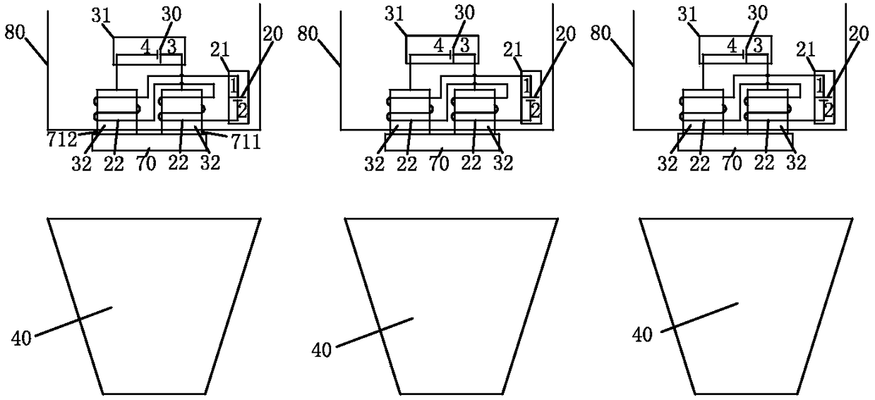
[0048] Such as figure 1 , 2, 3, 4, and 5, the microchip transfer system includes a storage device 10, a pick-up device, an electrical test device, an optical test device 40, a delivery device 50, a receiving device 60 and a carrier 80. The pick-up device and the electrical testing device are fixedly installed on the carrier 80 . In this embodiment, each carrier is provided with a pick-up device and an electrical testing device.

[0049] The storage device 10 is used for storing microchips 70 to be picked. The pick-up device is used to pick up the microchip 70 from the storage device 10 , or release the picked-up microchip 70 . The electrical testing device is used for testing the electrical performance of the microchip 70 picked up by the picking device. When the electrical testing device detects that the electrical performance of the microchip 70 picked up by the pick-up device is unqualified, the pick-up device will release the microchip 70 with unqualified electrical per...

Embodiment 2

[0079] Such as Figure 7 As shown, the difference between this embodiment and the first embodiment is that the test electrode 32 of the electronic test device is not inserted into the solenoid 22 of the pick-up device. The magnetic suction nozzle of pick-up device comprises power circuit 21, solenoid 22 and the metal core 23 that inserts solenoid 22, and metal core 23 is made by metal material, as iron; Microchip 70 comprises two magnetic pins 72; Microchip The first chip electrode 711 and the second chip electrode 712 of 70 are not magnetic, and are not magnetic pins.

[0080] When the magnetic suction nozzle of the pick-up device attracts the magnetic pins 72 of the microchip 70 by magnetic force, the first chip electrode 711 and the second chip electrode 712 of the microchip 70 are respectively connected with the two test electrodes 32 of the electronic testing device. The electrical performance of the microchip 70 picked up by the pick-up device can be tested without posi...

Embodiment 3

[0088] The difference between this embodiment and the first embodiment is that the distribution device 50 is a mechanical arm capable of translation and flipping.


PUM


Abstract

The invention discloses a microchip transfer system, which comprises a storage device used for placing a microchip, a pickup device used for picking up the microchip, an electrical testing device usedfor testing the microchip and a receiving device used for receiving the microchip, wherein the electrical testing device comprises a test electrode and a test circuit, one end of the test electrode is connected with the test circuit, and the other end is a free end; the microchip comprises a chip electrode and is characterized by further comprising a carrier; the electrical testing device and thepickup device are fixedly installed on the carrier; and the free end of the test electrode is connected with the chip electrode when the pickup device picks up the microchip. The pickup device and the electrical testing device are fixedly installed on the carrier, so that the electrical testing device is enabled to test the electrical performance of the microchip picked up by the pickup device without a positioning operation, and the risk of errors caused by inaccurate positioning of the electrical testing device is reduced.

Description

technical field [0001] The invention relates to the technical field of microchip transfer, in particular to a microchip transfer system and method. Background technique [0002] A microchip refers to a chip whose size reaches the order of microns. After the microchips are manufactured, they are generally transferred to a receiving device to form an array. How to transfer the microchip from the donor substrate to the receiving substrate is a problem to be solved by those skilled in the art. [0003] The invention patent with the publication number CN106601657A discloses a micro-component transfer device, transfer method, manufacturing method, device and electronic equipment, wherein the micro-component transfer system includes: a main pick-up device for picking up or releasing micro-components; testing The device has a test platform and a series of test circuits, and a series of test electrodes are arranged on the surface of the platform, which is connected with the test ci...

Claims


Application Information

Patent Timeline
Patent Type & Authority Applications(China)
IPC IPC(8): G01R31/28G01M11/00
CPCG01M11/00G01R31/2851G01M11/02G01R31/2893
Inventor 杨涛陶贤文许晋源
Owner HUIZHOU THORLED OPTO
Learn More