
Pipeline leakage monitoring system and method based on sound wave and negative pressure wave hybrid monitoring

A technology for pipeline leakage and mixed monitoring, applied in pipeline systems, by measuring the rate of increase and deceleration of fluid, and by detecting the appearance of fluid at the leak point, etc., it can solve the problems of easy false negatives, confusion, and inability to detect multiple leaks.

Active Publication Date: 2018-09-04
NORTHEASTERN UNIV
View PDF8 Cites 18 Cited by
  • Summary
  • Abstract
  • Description
  • Claims
  • Application Information

AI Technical Summary

Problems solved by technology

Among them, the negative pressure wave method is the most widely used pipeline leakage detection method in the world in recent years. This method has the characteristics of short reaction time and wide range of detectable leakage. The internal pressure changes slowly, and the negative pressure wave method is less sensitive to it, which is prone to false positives. Moreover, due to the complex working condition adjustment of the pipeline transportation system, some common operations such as the start and stop of the main pump, the opening and closing of the valve, and the regulating valve Changes in the opening will cause negative pressure waves, which have a high degree of similarity with negative pressure waves caused by leakage, which reduces the detection accuracy of the negative pressure wave method
[0004] Acoustic detection method leak detection has good monitoring accuracy for slow and small flow leakage, but it is easy to confuse the leakage with the abnormal sound wave caused by human or environmental factors, and this method cannot detect simultaneous multi-point leakage

Method used


Image

  • Pipeline leakage monitoring system and method based on sound wave and negative pressure wave hybrid monitoring
  • Pipeline leakage monitoring system and method based on sound wave and negative pressure wave hybrid monitoring
  • Pipeline leakage monitoring system and method based on sound wave and negative pressure wave hybrid monitoring

Examples


Embodiment Construction

[0123] The specific implementation manners of the present invention will be further described in detail below in conjunction with the accompanying drawings and embodiments. The following examples are used to illustrate the present invention, but are not intended to limit the scope of the present invention.

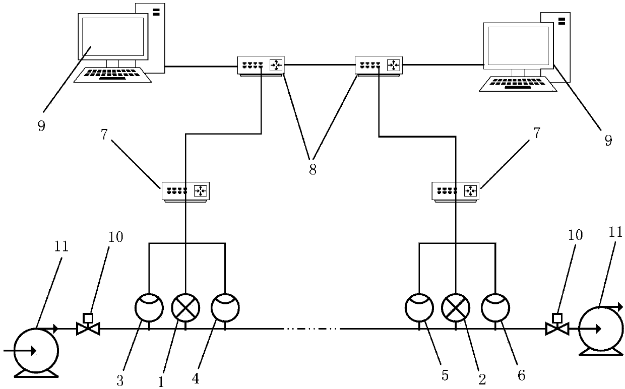
[0124] A pipeline leakage monitoring system based on acoustic negative pressure wave hybrid monitoring, such as figure 1 As shown, it includes a pressure sensor, an acoustic wave sensor, a lower computer 7, a switch 8 and an upper computer 9.

[0125] A pressure sensor is installed at the beginning and end of the pipeline, and is in contact with the conveying medium, and is used to collect high-precision data reflecting the pipeline pressure in real time. The pressure sensors at the beginning and end of the pipeline are as follows: figure 1 1 and 2 in.

[0126] In this embodiment, the main parameters of the Rosemount 3051s pressure transmitter are as follows:

[0127] ...


PUM


Abstract

The invention provides a pipeline leakage monitoring system and method based on sound wave and negative pressure wave hybrid monitoring, and relates to the technical field of pipeline risk prediction.The system comprises pressure sensors, sound wave sensors, lower computers, exchangers and upper computers which are located at the head end and the tail end of a pipeline, wherein the lower computers control the pressure sensors and the sound wave sensors to acquire pressure and sound wave data, preprocess the pressure and sound wave data and then send the pressure and sound wave data to the upper computers through the exchangers, and the upper computers execute leakage monitoring programs in the upper computers, receive and analyze the pressure and sound wave data transmitted by the lower computers through pressure and sound wave data integration and storage modules, carry out secondary filtering, dimensionless processing and semi-supervised Fisher discriminant analysis processing on the acquired data through data processing module, judge whether the pipeline leaks or not through pipeline leakage monitoring modules, and carry out hybrid positioning on the pressure signals and the sound wave signals. According to the pipeline leakage monitoring system and method, noise interference can be better shielded, when a signal source is changed, the accuracy of the restored signals afterfiltering can be guaranteed, and positioning of leakage points can be more accurate.

Description

technical field [0001] The invention relates to the technical field of pipeline risk prediction, in particular to a pipeline leakage monitoring system and method based on acoustic negative pressure wave hybrid monitoring. Background technique [0002] The role of pipeline transportation in economic development is becoming more and more important, such as urban water pipelines, land crude oil pipelines, submarine oil and gas pipelines, etc. Most of the oil transportation is transported in the pipeline in the form of refined oil. With the expansion of the pipeline network year by year, pipeline transportation has become the main mode of land oil and gas transportation. However, the aging, corrosion, sudden natural disasters and man-made damage of the pipeline will all cause the leakage or even rupture of the refined oil pipeline. If it is not discovered and stopped in time, it will not only cause energy waste, economic loss, environmental pollution, but also endanger personal ...

Claims


Application Information

Patent Timeline
IPC IPC(8): F17D5/06G01M3/24G01M3/28
Inventor 马大中张化光冯健汪刚刘金海于洋刘富聪关勇
Owner NORTHEASTERN UNIV
Learn More