Flat plate printing equipment

A technology of lithographic printing and equipment, applied in the field of lithographic printing equipment, can solve the problems of reduced work efficiency, easy to smudge the printing surface, poor printing effect, etc., and achieve the effect of improving efficiency

Active Publication Date: 2018-09-04
普天印务(重庆)股份有限公司
View PDF6 Cites 0 Cited by
  • Summary
  • Abstract
  • Description
  • Claims
  • Application Information

AI Technical Summary

Problems solved by technology

[0004] Although the above-mentioned patented scheme overcomes the defects of the roll printing machine when printing packaging materials, there are still some points to be improved in this scheme: 1. In the printing process, the printing plate is brushed with ink by the brush, but the printing plate There are uneven printing on the surface, which is prone to uneven ink brushing, resulting in poor printing effect; 2. After printing, the ink on the material has not been completely dry, and there is no drying mechanism in this plan. If at this time It is easy to stain the printing surface when picking and placing, which will lead to printing failure; if the ink on the material is completely dry before picking and placing, it will undoubtedly increase the time of the entire printing process and reduce work efficiency

Method used


Image

  • Flat plate printing equipment

Examples


Embodiment Construction

[0018] The present invention will be further described in detail below through specific implementations:

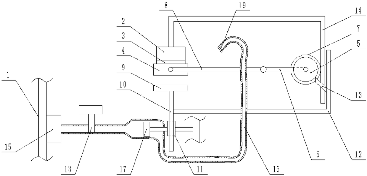
[0019] The reference signs in the drawings of the specification include: frame 1, printing machine base 2, printing plate 3, worktable 4, ratchet wheel 5, crank 6, first gear 7, connecting rod 8, ink tray 9, rack 10, The second gear 11, the supporting rod 12, the pawl 13, the transmission rod 14, the air supply box 15, the air guide tube 16, the turbine 17, the programmable valve 18, and the homogenizing plate 19.

[0020] This embodiment is basically as attached figure 1 Shown:

[0021] The lithographic printing equipment includes a frame 1. A printer base 2 is slidably connected to the frame 1, and a printing plate 3 is detachably fixed on the printer base 2. The detachable method is preferably bolted or clipped. 1 is connected to the upper sliding table 4, the sliding direction of the working table 4 and the printing machine base 2 is perpendicular, the rack 1 is rotatably ...


PUM


Abstract

The invention relates to the technical field of printing and discloses flat plate printing equipment. The flat plate printing equipment comprises a rack. A printing machine seat is connected with therack in a sliding mode, a forme is fixed on the printing machine seat, and a working table is connected with the rack in a sliding mode. The working table is vertical to the sliding direction of the printing machine seat. A ratchet wheel is rotatably connected with the rack. A crank and a first gear are coaxially connected with the ratchet wheel. A connecting rod is rotatably connected with the crank. One end of the connecting rod is rotatably connected to the working table. An ink plate is connected with the rack in a sliding mode, the ink plate is located under the printing machine seat, anda spline is fixed on the ink plate. A second gear meshed with the spline is rotatably connected with the rack. A driving mechanism for driving the second gear to rotate intermittently is arranged onthe rack. A supporting rod is fixed on the spline. A ratchet pawl meshed with the ratchet wheel is fixed on the supporting rod. A transmission rod is fixed on the printing machine seat, wheel teeth are arranged on the transmission rod, and the transmission rod is meshed with the first gear by the wheel teeth. According to the flat plate printing equipment, ink feeding can be automatically and uniformly carried out, and meanwhile ink on materials can be dried quickly.

Description

Technical field [0001] The present invention relates to the field of printing technology, in particular to a flatbed printing device. Background technique [0002] Packaging materials usually need to be printed with specific patterns or characters, and in the prior art, a roller printer is often used to print the packaging materials. However, when printing on paper or film packaging materials, slipping and jams are likely to occur, resulting in poor printing quality; for thicker materials such as corrugated paper and wood materials, it is difficult to print through rollers and the printing effect is not good. [0003] In order to solve the above problems, the Chinese patent (CN105109197B) discloses a packaging printing equipment, including a workbench, a feeding mechanism, an unloading mechanism, a sensor, a column, a printing press base, a printing press, an inking device and a controller; There are two uprights on both sides of the printer, and the four uprights are arranged in ...

Claims


Application Information

Patent Timeline
Patent Type & Authority Applications(China)
IPC IPC(8): B41F17/00B41F23/04B41F31/08B41F31/20
CPCB41F17/00B41F23/0443B41F31/08B41F31/20
Inventor 唐军民
Owner 普天印务(重庆)股份有限公司
Why Eureka
Try Eureka