
Electronic disc brake

A disc brake, electronic technology, applied in the direction of brake type, axial brake, brake components, etc., can solve the problems of large vibration and noise of the actuator, poor assembly and price competitiveness, and achieve compact size, Compact size and low noise operation, anti-reverse effect

Active Publication Date: 2018-08-28
HL MANDO CORP
View PDF12 Cites 5 Cited by
  • Summary
  • Abstract
  • Description
  • Claims
  • Application Information

AI Technical Summary

Problems solved by technology

[0004] With reference to the patent document Korea Laid-Open Patent No. 10-2011-0072877 (June 29, 2011), the document relates to the MOC type electronic parking brake actuator structure, the motor generating power is connected to the actuator, and multiple This gear unit decelerates the power generated by the motor while increasing the torque and transmits it to the actuator and caliper to perform the braking operation, however, the actuator used for this electronic disc brake generates a large Vibration and noise, poor assembly and price competitiveness

Method used


Image

  • Electronic disc brake
  • Electronic disc brake
  • Electronic disc brake

Examples


Embodiment Construction

[0035] Embodiments of the present invention will be described in detail below with reference to the drawings. The embodiments described below are illustrations for fully conveying the idea of ​​the present invention to those skilled in the art to which the present invention pertains. The present invention is not limited to the Examples described below, but may be embodied in other forms. In order to clearly illustrate the present invention, parts irrelevant to the description are omitted in the drawings, and for convenience of description, the width, length, thickness, etc. of components in the drawings may be enlarged. The same reference numerals refer to the same components throughout the specification.

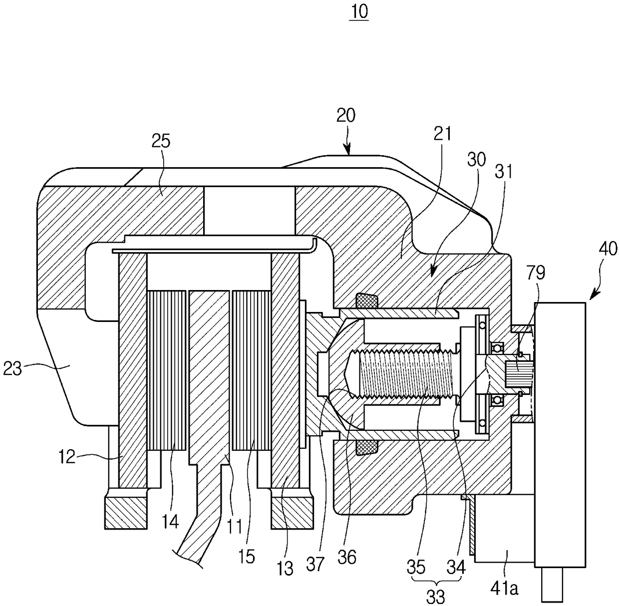
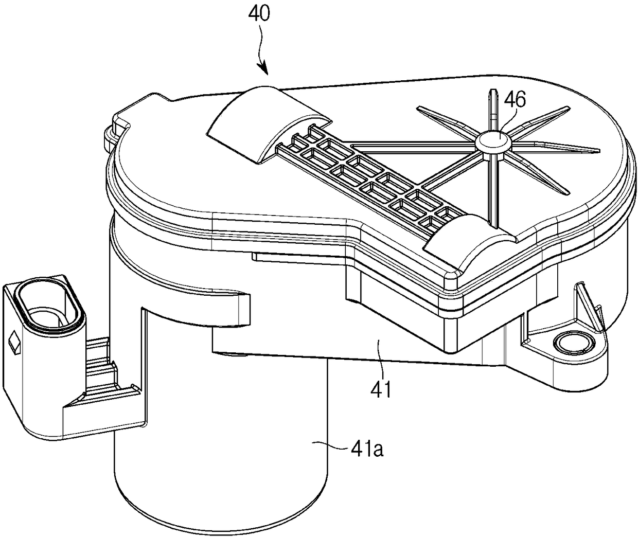
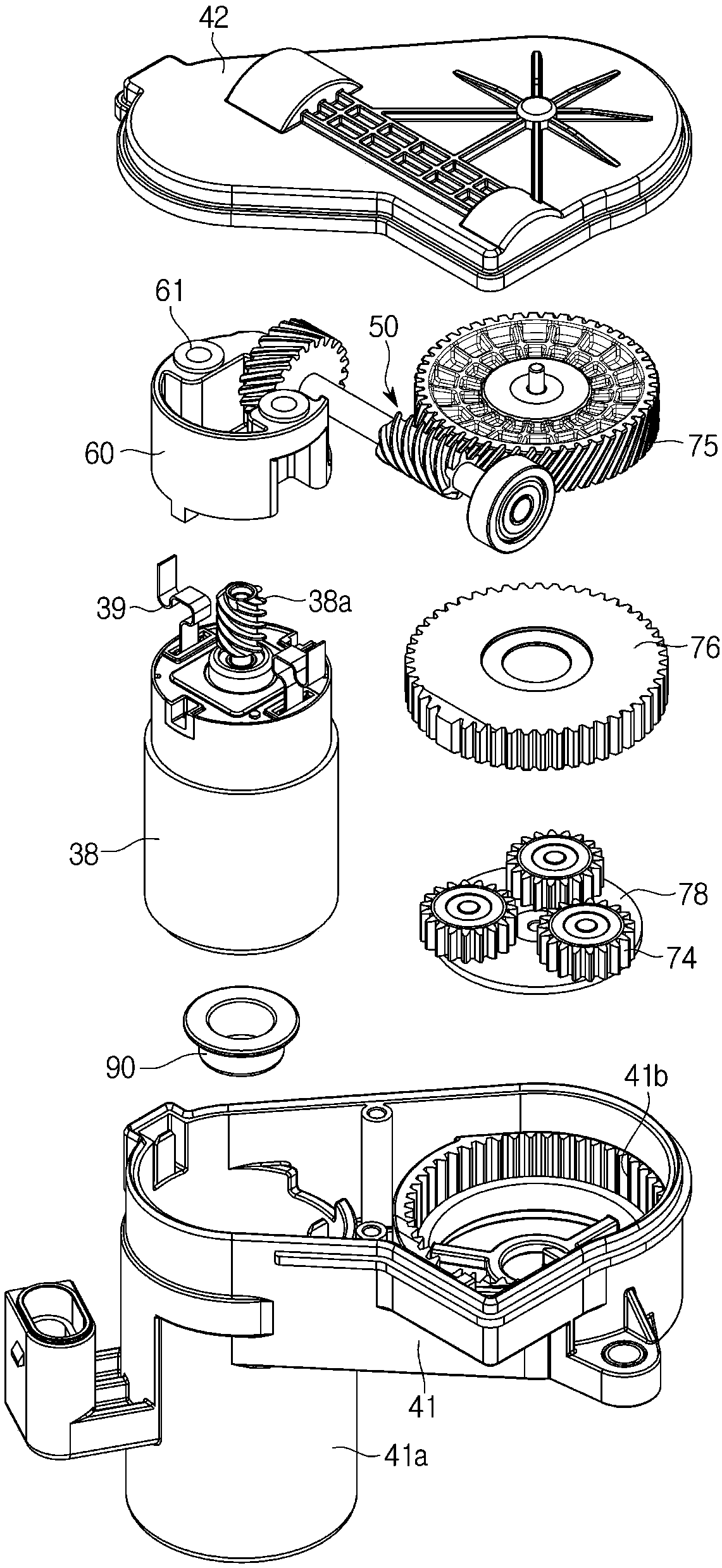
[0036] figure 1 is a cross-sectional view of an electronic disc brake showing an embodiment of the present invention, figure 2 is a perspective view of a reduction gear 40 according to an embodiment of the present invention, image 3 An exploded view of the reduction g...


PUM


Abstract

Disclosed herein is an electronic disc brake. The electronic disc brake according to one embodiment of the present disclosure includes a disc configured to be rotated with a wheel, a caliper housing configured to operate pad plates installed at both sides of the disc, and an actuator including a piston provided in the caliper housing and configured to press the pad plates to bring the pad plates into contact with the disc, a spindle rotatably installed in the caliper housing to move the piston forward and backward, a motor configured to rotate the spindle, and a speed reduction apparatus configured to transmit a rotational force of the motor to the spindle, wherein the speed reduction apparatus includes a power connecting unit connected to the motor, a bracket provide above the motor and configured to support the power connecting unit, and a speed reduction gear unit configured to sequentially connect the power connecting unit and the spindle.

Description

technical field [0001] The present invention relates to an electronic disc brake, and in more detail, relates to an electronic braking system capable of realizing the parking function through the operation of a motor. Background technique [0002] Generally speaking, the brake device is a device used to stop the vehicle when braking or parking to prevent the vehicle from moving, and it plays the role of fixing the wheels to prevent them from rotating. [0003] In recent years, an Electronic Parking Brake (EPB) system that drives a parking brake by electronic control, which is mounted on a conventional disc brake to perform a parking brake function, is widely used. Electronic disc brakes include a Cable Puller type, a Motor-On-Caliper (MOC) type, and a Hydraulic Parking Brake type. [0004] With reference to the patent document Korea Laid-Open Patent No. 10-2011-0072877 (June 29, 2011), the document relates to the MOC type electronic parking brake actuator structure, the mot...

Claims


Application Information

Patent Timeline
Patent Type & Authority Applications(China)
IPC IPC(8): F16D55/226F16D65/095F16D65/14F16H1/20F16H57/023F16H57/028F16D121/04F16D125/20
CPCF16D55/226F16D65/095F16D65/14F16H1/203F16H1/206F16H57/023F16H57/028F16D2121/04F16D2125/20F16D65/18F16D2121/14F16D2121/24F16D2125/40F16D2125/50F16D2125/52F16H1/28
Inventor 宋浚圭
Owner HL MANDO CORP
Learn More