
Prefabricated pre-stressed beam member, fabricated combined frame structure and installation method of fabricated combined frame structure

A technology for prestressed beams and frame structures, which is applied to structural elements, building components, and elongated structural components for load-bearing, etc. On-site installation of beam-column joints requires a lot of work and high requirements for positioning of protruding steel bars, so as to achieve the effect of high binding installation efficiency, saving measures cost, and high production efficiency

Pending Publication Date: 2018-08-28
SOUTHEAST UNIV +2
View PDF0 Cites 10 Cited by
  • Summary
  • Abstract
  • Description
  • Claims
  • Application Information

AI Technical Summary

Problems solved by technology

However, the prefabricated columns of the assembled concrete frame structure are prefabricated in layers, and the cost of vertical steel connection is high, and the large cross-section columns increase the cost of transportation and hoisting measures; heavy workload
The installation process of steel frame structure is safe, reliable and mature, but the durability, fire resistance and sound insulation of steel structure are not satisfactory, and the economy is worse than that of concrete frame structure

Method used


Image

  • Prefabricated pre-stressed beam member, fabricated combined frame structure and installation method of fabricated combined frame structure
  • Prefabricated pre-stressed beam member, fabricated combined frame structure and installation method of fabricated combined frame structure
  • Prefabricated pre-stressed beam member, fabricated combined frame structure and installation method of fabricated combined frame structure

Examples


Embodiment Construction

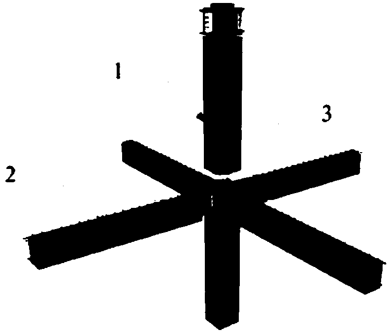
[0034] Such as figure 1 , the prefabricated composite frame structure of the present invention includes a prefabricated column member 1 having a beam-column joint area 3 , a prefabricated prestressed beam member 2 and a prefabricated bottom slab 19 of a laminated floor. The interior of the prefabricated column member 1 is a hollow steel pipe 4 . The prefabricated composite frame structure also includes cast-in-place concrete in the prefabricated column hollow steel pipe 4 and superimposed surface layer concrete. Among them, the cast-in-place concrete in the prefabricated column hollow steel pipe 4 is poured after the prefabricated column member 1 is transported to the construction site; The prefabricated bottom slab 19 of the laminated floor is placed on the prefabricated prestressed beam member 2 and poured together with the beam-column node area 3 .

[0035] Such as Figures 2(a) to 2(d) , the middle section of the hollow steel pipe 4 of the prefabricated column member 1 ...


PUM


Abstract

The invention discloses a prefabricated pre-stressed beam member, a fabricated combined frame structure and an installation method of the fabricated combined frame structure. The fabricated combined frame structure comprises prefabricated column members with hollow steel pipes inside, prefabricated pre-stressed beam members, cast-in-place concrete inside the prefabricated column hollow steel pipes, a laminated floor slab prefabricated base plate and laminated surface layer concrete. The middle sections of the hollow steel pipes of the prefabricated column members are covered with concrete, anda beam-column joint zone provided with short H-shaped steel beams is arranged at both ends of each middle section. The prefabricated pre-stressed beam member comprises a concrete laminated pre-stressed beam and interposed H-shaped steel beams at both ends of the pre-stressed beam. The short H-shaped steel beams in the beam-column joint zone and the interposed H-shaped steel beams of the prefabricated pre-stressed beam member are combined by bolt welding or connected by bolting. Joints of the hollow steel pipes of the upper and lower sections of the prefabricated column members are connected by welding. The fabricated combined frame structure integrates the advantages of a steel structure and a prefabricated concrete structure, and has high installation efficiency and good safety, and manpower and material resources are greatly saved.

Description

technical field [0001] The invention relates to a prefabricated prestressed beam component, an assembled composite frame structure and an installation method, and belongs to the technical field of steel-concrete composite frame structures in construction engineering. technical background [0002] Prefabricated concrete frame structures are used in public buildings such as schools, hospitals, and office buildings, as well as in underground space structures and subway stations. The use of prefabricated concrete frame structures can reduce environmental pollution, save labor and improve construction quality. However, the prefabricated columns of the assembled concrete frame structure are prefabricated in layers, and the cost of vertical steel connection is high. The self-heavyness of the large cross-section columns will increase the cost of transportation and hoisting measures; A lot of work. The installation process of steel frame structure is safe, reliable and mature, but ...

Claims


Application Information

Patent Timeline
Patent Type & Authority Applications(China)
IPC IPC(8): E04C3/293E04B1/19
CPCE04B1/19E04C3/293
Inventor 郭正兴杨森管东芝朱明亮
Owner SOUTHEAST UNIV
Learn More