Display module and electronic equipment

A display module and electrode technology, applied in the direction of instruments, nonlinear optics, optics, etc., can solve the problems of long response time, limitation of electronic ink display technology, easy reunion, etc., and achieve reduced movement distance and good reflective display effect , to ensure the effect of the display effect

Active Publication Date: 2020-07-31
BOE TECH GRP CO LTD +1
View PDF10 Cites 0 Cited by
  • Summary
  • Abstract
  • Description
  • Claims
  • Application Information

AI Technical Summary

Problems solved by technology

[0003] However, when the electronic ink particles of the existing electronic ink screen move under the action of electrodes, they are prone to agglomeration and the reaction time is long, which limits the application of electronic ink display technology and cannot be used in high-end electronic devices. superior

Method used


Image

  • Display module and electronic equipment
  • Display module and electronic equipment
  • Display module and electronic equipment

Examples


Embodiment 1

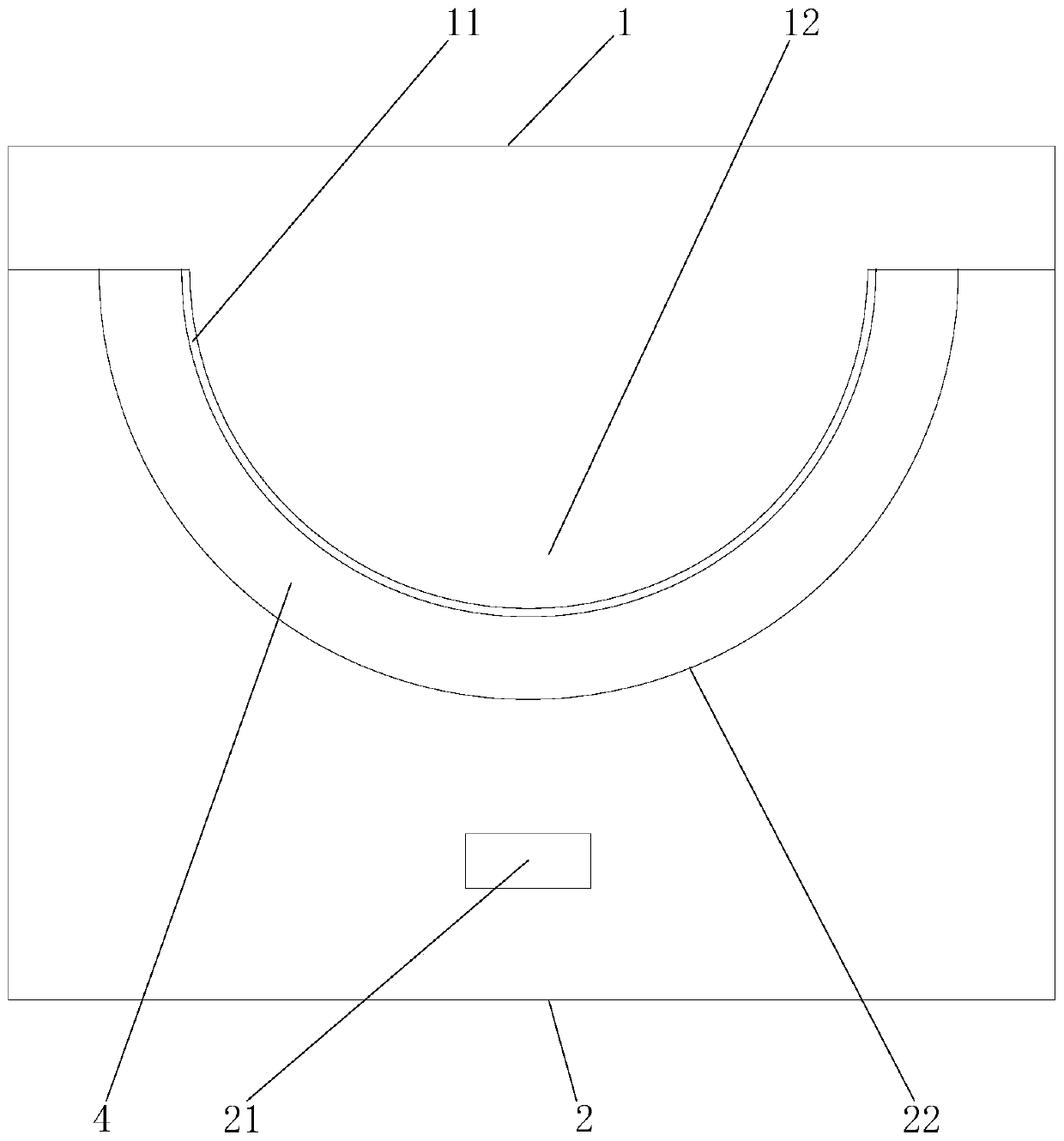
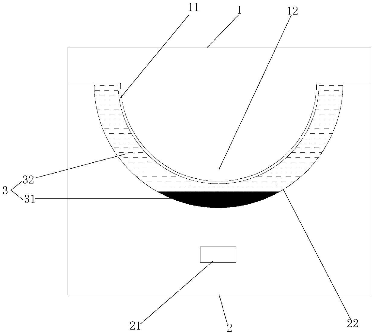
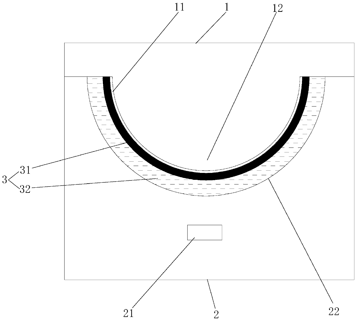
[0046] like Figure 1-Figure 3 As shown, a display module proposed in Embodiment 1 of the present invention includes: an upper substrate 1, a lower substrate 2, and an inverse emulsion 3; the upper substrate 1 is provided with a first electrode 11, and the upper substrate 1 The first surface is provided with a plurality of arc-shaped protrusions 12 arranged in a matrix; the lower substrate 2 is provided with a second electrode 21, and the first surface of the lower substrate 2 is provided with a plurality of arc-shaped grooves arranged in a matrix 22; wherein, the first surface of the upper substrate 1 is attached to the first surface of the lower substrate 2, and each of the arc-shaped protrusions 12 cooperates with one of the arc-shaped grooves 22 to form a groove shape The accommodation space 4 , the inverse emulsion 3 is filled in the tank-shaped accommodation space 4 .

[0047]The display module provided by the present invention is similar to the display principle of the...

Embodiment 2

[0065] An electronic device proposed in Embodiment 2 of the present invention includes: a display module; Figure 1-Figure 3 As shown, the display module includes: an upper substrate 1, a lower substrate 2 and an inverse emulsion 3; the upper substrate 1 is provided with a first electrode 11, and the first surface of the upper substrate 1 is provided with a plurality of Arc-shaped protrusions 12; the lower substrate 2 is provided with a second electrode 21, and the first surface of the lower substrate 2 is provided with a plurality of arc-shaped grooves 22 arranged in a matrix; wherein, the upper substrate 1 The first surface is attached to the first surface of the lower substrate 2, and each of the arc-shaped protrusions 12 cooperates with one of the arc-shaped grooves 22 to form a groove-shaped accommodation space 4, which is filled with the inverse emulsion 3 In the groove-shaped accommodation space 4 .


PUM

PropertyMeasurementUnit
thicknessaaaaaaaaaa
thicknessaaaaaaaaaa
diameteraaaaaaaaaa

Abstract

The invention relates to a display module and electronic equipment, and relates to the field of display technology. The technical problem to be solved is to solve the problem of agglomeration of charged particles on an electronic ink screen and to speed up the display response speed. The technical solution mainly adopted is: a display module, which includes: an upper substrate, the upper substrate is provided with a first electrode, the first surface of the upper substrate is provided with a plurality of arc-shaped protrusions arranged in a matrix; the lower substrate , the lower substrate is provided with a second electrode, the first surface of the lower substrate is provided with a plurality of arc-shaped grooves arranged in a matrix; an inverse emulsion; wherein, the first surface of the upper substrate and the first surface of the lower substrate A surface fit, each of the arc-shaped protrusions cooperates with one of the arc-shaped grooves to form a groove-shaped accommodation space, and the reverse emulsion is filled in the groove-shaped accommodation space. The display module provided by the invention can avoid the agglomeration of charged particles and accelerate the display response speed.

Description

technical field [0001] The invention relates to the field of display technology, in particular to a display module and electronic equipment. Background technique [0002] The electronic ink screen is composed of two substrates, and an electronic ink composed of countless tiny transparent particles is coated between the substrates. The particles are formed by sealing many black and white particles with positive and negative charges in the internal liquid microcapsules. Different colors Charged particles will move in different directions due to different applied electric fields, showing black or white effect on the surface of the display screen, with high reflectivity and clear display effect; and the display of electronic ink screen is through the charged particles. Light reflection is used for display, and images can be continuously displayed without continuous power supply, which has the effect of energy saving and power saving. [0003] However, when the electronic ink pa...

Claims


Application Information

Patent Timeline
Patent Type & Authority Patents(China)
IPC IPC(8): G02F1/167G02F1/1679G02F1/1676G02F1/16757G02F1/1681
CPCG02F1/167G02F1/1681G02F2203/023G02F1/157G02F1/16757
Inventor 吕振华王志东徐晓玲尤杨贾宁邱云
Owner BOE TECH GRP CO LTD
Why Eureka
Try Eureka