
Ammonia concentration distribution test device

A technology of distribution testing and ammonia gas concentration, which is applied to the electronic control of exhaust gas treatment devices, diagnostic devices of exhaust gas treatment devices, and exhaust gas treatment, etc. problems, to achieve the effect of convenient operation, high measurement accuracy and comprehensive measurement data

Active Publication Date: 2018-08-24
JIANGSU TIANHAI SPECIAL EQUIPMENT CO LTD
View PDF5 Cites 4 Cited by
  • Summary
  • Abstract
  • Description
  • Claims
  • Application Information

AI Technical Summary

Problems solved by technology

[0003] At present, because the ammonia concentration distribution test of the SCR system is in the gas phase, the point test method is generally used. By collecting the gas phase substances flowing through the point, the concentration of the point is obtained by Fourier transform infrared spectrum FTIR analysis. The test range is not comprehensive enough. The point layout process It is cumbersome and cannot obtain transient data, and there is no test device that can fully and accurately reflect the concentration distribution on the entire cross-section

Method used


Image

  • Ammonia concentration distribution test device
  • Ammonia concentration distribution test device
  • Ammonia concentration distribution test device

Examples


Embodiment Construction

[0022] The present invention will be described in further detail below in conjunction with the accompanying drawings and specific embodiments, but the protection scope of the present invention is not limited thereto.

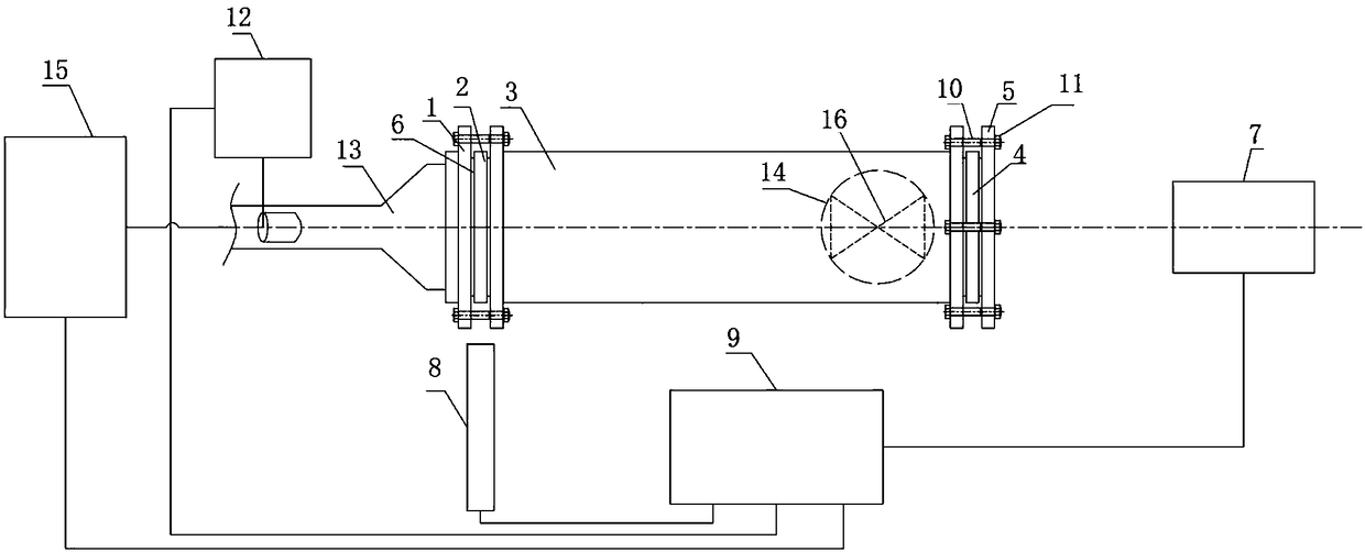
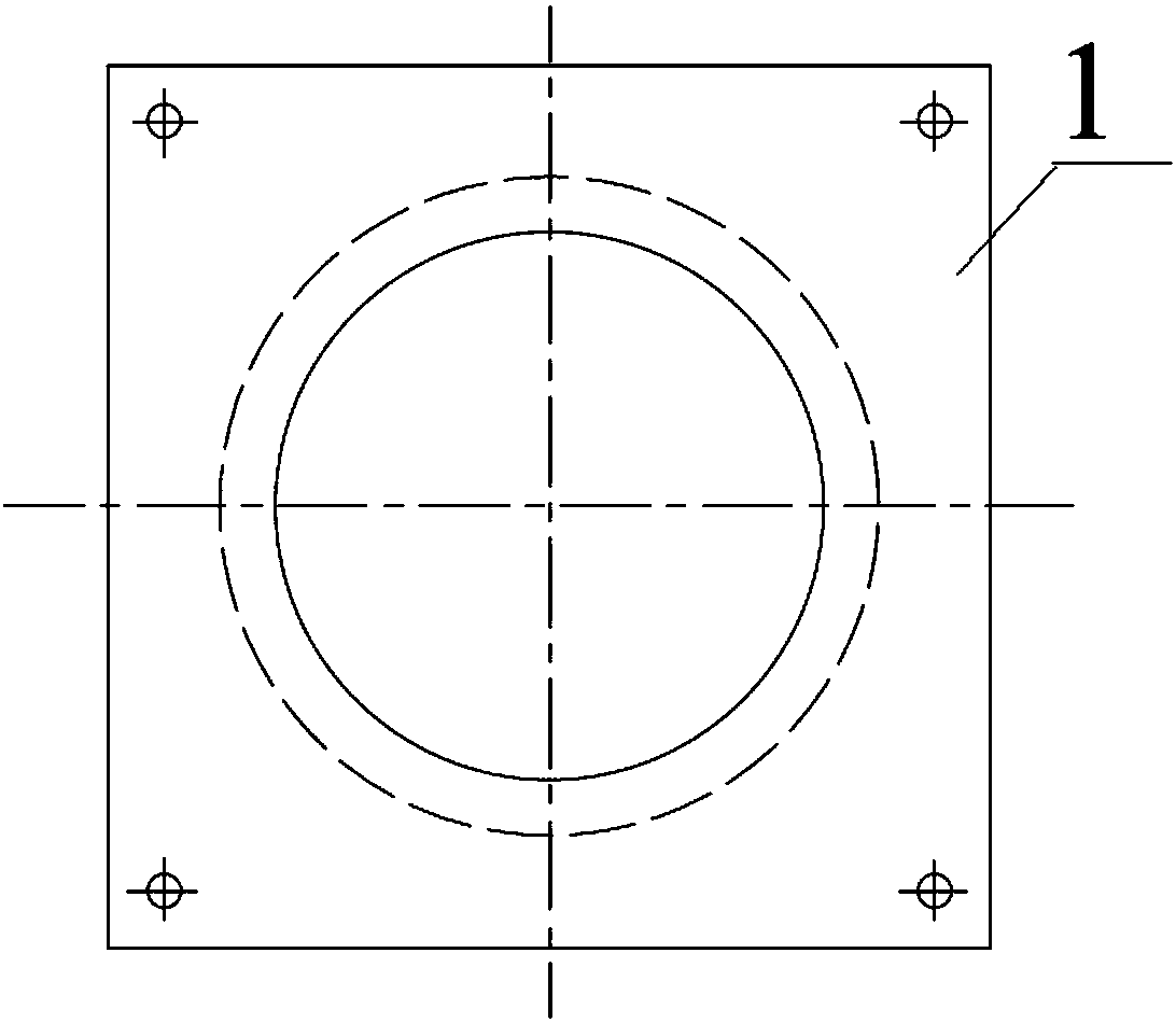
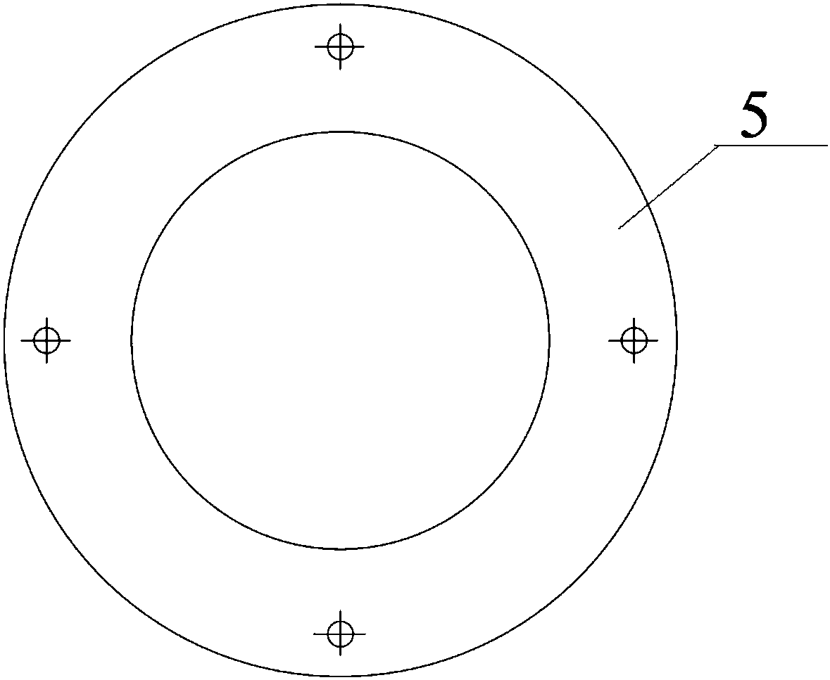
[0023] Such as figure 1 As shown, the preferred embodiment of the present invention mainly includes an image capture device, a controller 9 , a laser 8 , a first glass block, a circular tube 3 , a second glass block and an air duct 14 .

[0024] The first glass block is installed on one end of the round tube 3, and the first glass block has a through hole communicating with one end of the round tube 3; the second glass block is installed on the other end of the round tube 3; 14 is connected with the exhaust port of the round pipe 3; the laser 8 is in the same plane as the first glass block, and the laser light emitted by the laser 8 enters the round pipe 3 through the first glass block; the image pickup device is connected with the first glass block On the same...


PUM


Abstract

The invention provides an ammonia concentration distribution test device. The ammonia concentration distribution test device comprises an image shooting device, a controller, a laser device, a first glass block, a circular pipe, a second glass block and a gas guide pipe, wherein the first glass block is installed at one end of the circular pipe, and is provided with a through hole communicated with one end of the circular pipe; the second glass block is installed at the other end of the circular pipe; the gas guide pipe is connected with the exhaust port of the circular pipe; the laser deviceand the first glass block are located in the same plane, and the laser emitted by the laser device enters into the circular pipe through the first glass block; the image shooting device, the first glass block and the second glass block are located on the same axis and mutually parallel, and the image shooting device acquires the fluorescent images generated by ammonia due to the effect of laser; and the laser device and the controller are connected with the controller separately. The system device is capable of realizing visual and quantitative test for ammonia concentration distribution on the whole section of the front end of a catalyst in an SCR system simultaneously, has the advantages of being high in measurement accuracy and comprehensive in test range, and plays the role of guidanceon the optimal design for the SCR system and an exhaust pipeline.

Description

technical field [0001] The invention belongs to the technical field of internal combustion engine testing, and mainly relates to an ammonia concentration distribution testing device; aiming at testing the ammonia concentration distribution at the front end of a catalyst in an SCR system after a diesel engine, the invention can comprehensively measure the concentration distribution on the entire cross section. Background technique [0002] SCR post-treatment technology is the key post-treatment technology for reducing NOx in diesel engines. Its working principle is to inject urea aqueous solution into the exhaust pipe exhaust gas to provide ammonia as a reducing agent, and at the same time, it can combine with NOx in the exhaust gas. x Reaction to achieve NO reduction x . Among them, the atomization decomposition of aqueous urea solution and the subsequent mixing with exhaust gas have a crucial impact on the performance of SCR, especially the uniformity of the ammonia concen...

Claims


Application Information

Patent Timeline
Patent Type & Authority Applications(China)
IPC IPC(8): F01N11/00
CPCF01N11/00F01N2610/02F01N2900/1818Y02T10/40
Inventor 尹必峰俞升浩文帅贾和坤
Owner JIANGSU TIANHAI SPECIAL EQUIPMENT CO LTD
Learn More