Fabricated building component connecting device

A technology for connecting devices and building components, applied in building structures, buildings, etc., can solve the problems of inability to withstand vertical tension and lateral forces, and achieve the effect of improving connection convenience, convenient detection, and structural strength.

Pending Publication Date: 2018-08-24
江培刚
View PDF0 Cites 0 Cited by
  • Summary
  • Abstract
  • Description
  • Claims
  • Application Information

AI Technical Summary

Problems solved by technology

[0005] The main technical problem to be solved by the present invention is to provide a connecting device for prefabricated building components, which solves the problems of connection quality and connection point detection of prefabricated concrete component components. There is no problem with the welding work surface in the connection method, ensuring that the parts that should be connected can be effectively connected, and solving the problem that the steel column in the steel structure prefabricated building cannot bear the vertical tension and lateral force in the connection method of planing and topping. The problem

Method used


Image

  • Fabricated building component connecting device
  • Fabricated building component connecting device

Examples


Embodiment 1

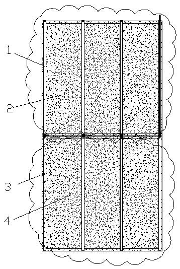
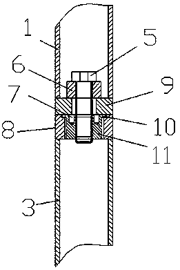
[0029] When the first member 2 and the second member 4 are prefabricated concrete members respectively, it is necessary to embed several first steel pipes 1 in the first member 2 and several second steel pipes 3 in the second member 4. The bottom of the steel pipe 1 and the second steel pipe 3 are respectively welded with a lower end plate 9 with a through hole, and the tops of the first steel pipe 1 and the second steel pipe 3 are respectively welded with an upper end plate 8 with a first internal threaded hole, and then the first steel pipe 1 And the second steel pipe 3 is poured into the corresponding concrete member to form the first member 2 and the second member 4. The specifications of the first member 2 and the second member 4 can be the same or different. After being in place, screw the nut 11 into the upper end plate 8 of the second steel pipe 3, and screw the bolt 5 in the first steel pipe 1 into the nut 11 of the second steel pipe 3 through the sleeve and the sleeve...

Embodiment 2

[0031] When the first component 2 and the second component 4 are steel structure assembled building components, the first steel pipe 1 is used to replace part of the steel columns in the first component 2, and the second steel tube 3 is used to replace part of the steel columns in the second component 4 First, weld a lower end plate 9 with a through hole at the bottom of the first steel pipe 1 and the second steel pipe 3 respectively, and weld an upper end plate 8 with the first threaded hole in the top of the first steel pipe 1 and the second steel pipe 3 respectively, and then A plurality of first members 2 and second members 4 of the same or different models are welded in the factory, screw nuts 11 into the upper end plate 8 of the second steel pipe 3, and insert the first steel pipe 1 through the sleeve and the sleeve rod. The bolt 5 is screwed into the nut 11 of the second steel pipe 3, thereby connecting the first steel pipe 1 and the second steel pipe 3 together, replaci...


PUM


Abstract

The invention discloses a fabricated building component connecting device, comprising first components, second components and component connecting devices. Each component connecting device comprises afirst steel tube, a second steel tube, nuts and bolts. The first steel tubes are respectively arranged in the first components, and the second steel tubes are respectively arranged in the second components and correspond to the first steel tubes end-to-end correspondingly. The tail ends of the first steel tubes and the second steel tubes are respectively provided with lower end plates, and the front ends of the first steel tubes and the second steel tubes are provided with upper end plates. A through hole is formed in each lower end plate. The bolts penetrate through the lower end plates fromthe first steel tubes and connect with the nuts in the upper end plates of the second steel tubes. According to the fabricated building component connecting device, the connection convenience of precast concrete fabricated building and steel construction fabricated building is improved, and the effective connection of the parts which should be joined of the steel construction fabricated buildingcomponents is ensured.

Description

technical field [0001] The invention relates to the technical field of construction, in particular to a connection device for assembled building components. Background technique [0002] At present, there are mainly three kinds of international and domestic prefabricated buildings: prefabricated concrete prefabricated buildings, steel structure prefabricated buildings and wood structure prefabricated buildings. Among them, the prefabricated concrete assembly building components are mainly connected by sleeve grouting, and the steel structure assembly building components are mainly connected by welding and steel column planing and top tightening. [0003] It is difficult to guarantee the quality of sleeve grouting connection of precast concrete assembly building components. The sleeve grouting connection of prefabricated concrete assembly building components, because the grouting in the sleeve cannot be seen, and there is currently no suitable means to detect the quality of ...

Claims


Application Information

Patent Timeline
IPC IPC(8): E04B1/38
CPCE04B1/388
Inventor 江培刚
Owner 江培刚
Why Eureka
Try Eureka