Ion source with temperature control function and operating method thereof

A working method and technology of ion source, applied in the field of ion source, can solve the problems of long cooling time, slow cooling time, low utilization rate, etc., and achieve the effects of accurate heating temperature control, stable ion beam and simple structure

Pending Publication Date: 2018-08-21
NINGBO UNIV +1
View PDF0 Cites 0 Cited by
  • Summary
  • Abstract
  • Description
  • Claims
  • Application Information

AI Technical Summary

Problems solved by technology

[0003] The current open ion source technology mainly has the following deficiencies: the ion source heat transfer heating technology can quickly realize the heating of the equal-diameter space, and due to the use of hollow air and external sealing, the heat loss is large and the utilization rate is not high. , when rapid cooling is required, the cooling time is too long, which makes the waiting time of the experiment too long; the ion source fan cooling technology, due to the discharge characteristics of the ion source, placing a fan outside the good heat preservation device is effective for high temperature in a short time, but in the medium The effect of the temperature section is not obvious, and the cooling time is slow, which makes it impossible to meet the technical requirements for rapid heating and cooling

Method used


Image

  • Ion source with temperature control function and operating method thereof

Examples


Embodiment 1

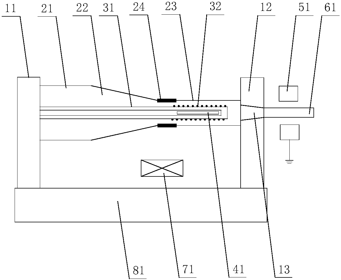
[0033] figure 1 A schematic structural diagram of an ion source with a temperature control function according to an embodiment of the present invention is schematically given, as shown in figure 1 As shown, the ion source with temperature control function includes:

[0034] A gas pipeline, the gas pipeline has a section 21 with a larger inner diameter, a transition section 22 and a section 23 with a smaller inner diameter arranged in sequence, and one end of the section with a larger inner diameter is fixed on the first bearing member;

[0035] a first section, the first section including the larger inner diameter section and a transition section;

[0036] The second part, the second part includes the section with a smaller inner diameter; the thermal conductivity of the first part is greater than that of the second part, for example, the first part is made of metal, and the second part is made of ceramics;

[0037] a connecting portion 24 connecting the first and second por...

Embodiment 2

[0060] An application example of the ion source with temperature control function described in Embodiment 1 of the present invention.

[0061] In this application example, the first part is made of stainless steel or Kovar alloy; the angle of the cone formed by the transition section is 30-60°; the angle of the cone formed by the second through hole is 30-60°; the temperature measuring part adopts Thermocouple, thermistor or platinum resistance (RTD); the cooling gas uses nitrogen or argon or air or helium; the delivery unit uses an air pump to deliver the gas to the outside of the connection between the transition section and the inner diameter section , so as to take away heat; at the same time, the heat of the smaller inner diameter section is conducted to the transition section.


PUM


Abstract

The invention provides an ion source with a temperature control function and an operating method thereof. The ion source comprises a high voltage electrode, a gas pipeline, a heating member, a temperature measuring component and a conveying unit, wherein the gas pipeline has a large inner diameter section, a transition section and a small inner diameter section which are arranged in sequence, oneend of the large inner diameter section is fixed on a first load-bearing member; the high voltage electrode is arranged at the side, which is away from the large inner diameter section, of the small inner diameter section; the heating member is arranged in the small inner diameter section; the temperature measuring component detects the temperature of a gas in the small inner diameter section; andthe conveying unit conveys the gas to the outer side of the junction of the transition section and the small inner diameter section. The ion source has the advantages of simple structure, fast heating, fast cooling and the like.

Description

technical field [0001] The invention relates to an ion source, in particular to an ion source with a temperature control function and a working method thereof. Background technique [0002] During the working process of the open ion source, when the high-temperature sample is ionized, the temperature of the discharge gas should be raised in a sealed environment without electronic interference to increase the ion velocity intensity and ion beam energy of the gas, which is conducive to the ionization of the sample. . When analyzing samples with a lower ionization temperature, the ion source needs to be cooled rapidly in a sealed environment to reach the expected temperature range. Therefore, the rapid realization of the temperature control of the ion source is conducive to the orderly and rational conduct of the experiment. [0003] The current open ion source technology mainly has the following deficiencies: the ion source heat transfer heating technology can quickly realiz...

Claims


Application Information

Patent Timeline
Patent Type & Authority Applications(China)
IPC IPC(8): H01J3/04
CPCH01J3/04
Inventor 洪欢欢闻路红赵鹏陈瑞强宁录胜
Owner NINGBO UNIV
Why Eureka
Try Eureka