Scaffold connector for civil engineering

A technology of civil engineering and scaffolding, which is applied to the accessories of scaffolding, building structure support, building structure support, etc. It can solve the problems of poor economy, inability to reuse, and safety, and achieve good knot effect, avoid water seepage hidden dangers, and solve The effect of poor rigidity

Inactive Publication Date: 2018-08-21
张松柯
View PDF0 Cites 0 Cited by
  • Summary
  • Abstract
  • Description
  • Claims
  • Application Information

AI Technical Summary

Problems solved by technology

The tie-brace combination method has low cost, convenient construction, and no post-masonry hole filling process. However, the tie bars only bear the tension, and the pressure is transmitted by the top support. Potential safety hazards are usually only used for scaffolds below 24m; the pre-embedded steel pipe method has good rigidity and accurate steel pipe embedding positions, and is currently the most common method of connecting wall parts, but the cost of steel pipes is high, disassembly is troublesome, and masonry The hole is left behind for later plugging. If the plugging is a little careless, the hole will not be filled tightly and cause water seepage. The post-anchoring method is improved to address the shortcomings of the pre-embedded steel pipe method. It not only has good rigidity and no holes to fill There is no hidden danger of water seepage in the process, but the construction process is extremely troublesome, especially the drilling, and after the construction is completed, the anchor bolts are also scrapped and cannot be reused, and the cost is relatively high; the hoop column method has good rigidity and flexible and convenient construction, but the hoop column method A lot of materials are required, and the economy is extremely poor. Like the embedded steel pipe method, there is also a hidden danger of water seepage

Method used


Image

  • Scaffold connector for civil engineering
  • Scaffold connector for civil engineering

Examples


Embodiment Construction

[0014] In order to make the object, technical solution and advantages of the present invention clearer, the present invention will be further described in detail below in conjunction with the accompanying drawings and embodiments. It should be understood that the specific embodiments described here are only used to explain the present invention, not to limit the present invention.

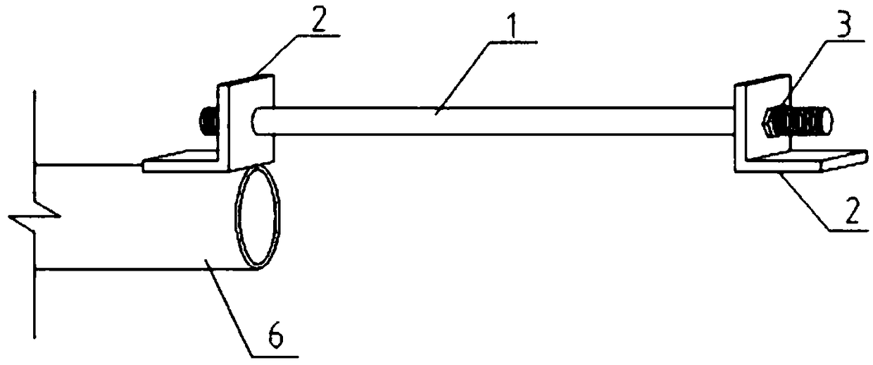
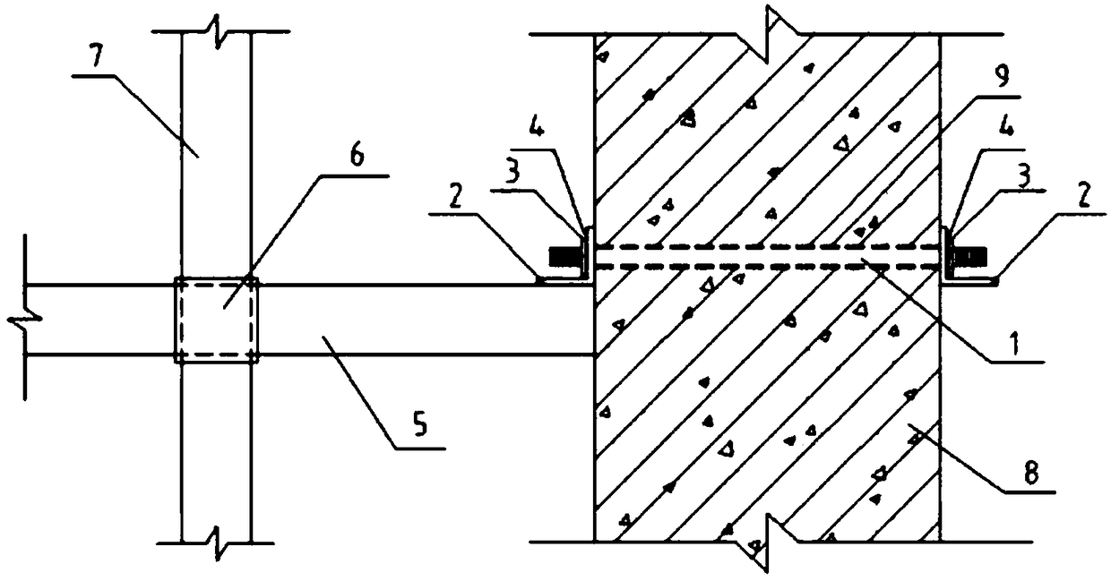
[0015] Such as figure 1 with figure 2 The shown civil engineering scaffold connector includes bolt 1, angle steel 2 and scaffold steel pipe 5, the bolt 1 runs through the reserved hole 9 of the outer wall 8, the scaffold steel pipe 5 is fixed on the scaffold pole 7, and the scaffold steel pipe 5 There is a section of angle steel 2 welded above the nozzle at one end, the end of the bolt 1 on the outside of the wall passes through the angle steel 2 on the scaffolding steel pipe 5, the end of the bolt 1 on the inside of the wall passes through another separate angle steel 2, and the bolt 1 and the a...


PUM


Abstract

The invention discloses a scaffold connector for civil engineering. The connector comprises bolts, angle steel and a scaffold steel pipe, the bolts penetrate through preformed holes of the outer wall,and the scaffold steel pipe is fixed to a scaffold vertical rod; a segment of angle steel is welded to the upper portion of a pipe opening of one end of the scaffold steel pipe, the ends of the boltsat the outer side of the wall penetrate through the angle steel on the scaffold steel pipe, and the ends of the bolts at the inner side of the wall penetrate through the other segment of separate angle steel; the bolts and the angle steel are screwed and fixed through nuts, spacers are arranged to protect the angle steel, the bolts are double-end bolts, and the scaffold steel pipe and the scaffold vertical rod are connected through a steel pipe fastener. The scaffold connector for civil engineering has the advantages that the connector is safe, stable, good in rigidity, easy to construct, convenient to disassemble and assemble, suitable for various structural forms and capable of not being limited by height, and the components can be recycled.

Description

technical field [0001] The invention relates to the technical field of civil engineering, in particular to a civil engineering scaffold connector. Background technique [0002] At present, the commonly used methods for connecting wall parts of external walls include tension-brace bonding method, pre-embedded steel pipe method, post-anchoring method and hoop column method, etc. The tie-brace combination method has low cost, convenient construction, and no post-masonry hole filling process. However, the tie bars only bear the tension, and the pressure is transmitted by the top support. Potential safety hazards are usually only used for scaffolds below 24m; the pre-embedded steel pipe method has good rigidity and accurate steel pipe embedding positions, and is currently the most common method of connecting wall parts, but the cost of steel pipes is high, disassembly is troublesome, and masonry The hole is left behind for later plugging. If the plugging is a little careless, th...

Claims


Application Information

Patent Timeline
Patent Type & Authority Applications(China)
IPC IPC(8): E04G5/04
CPCE04G5/046
Inventor 张松柯
Owner 张松柯
Why Eureka
Try Eureka