A sensor welding jig

A welding fixture and sensor technology, applied in welding equipment, laser welding equipment, manufacturing tools, etc., can solve the problems of reducing production efficiency, increasing production cost, unsightly welding seam, etc., achieving high production efficiency, zero scrap rate, welding Reliable quality results

Active Publication Date: 2019-12-27
WUHAN CHUTIAN IND LASER EQUIP
View PDF8 Cites 0 Cited by
  • Summary
  • Abstract
  • Description
  • Claims
  • Application Information

AI Technical Summary

Problems solved by technology

[0002] There are manual welding, laser welding, etc. for the welding of sensors in the existing technology, but the welding efficiency is low, the labor intensity is low, the welding quality is low, the weld seam is not beautiful, and the scrap rate is high, which increases the production cost and reduces the production efficiency.

Method used


Image

  • A sensor welding jig
  • A sensor welding jig
  • A sensor welding jig

Examples


Embodiment Construction

[0030] The following examples are used to illustrate the present invention, but are not intended to limit the scope of the present invention.

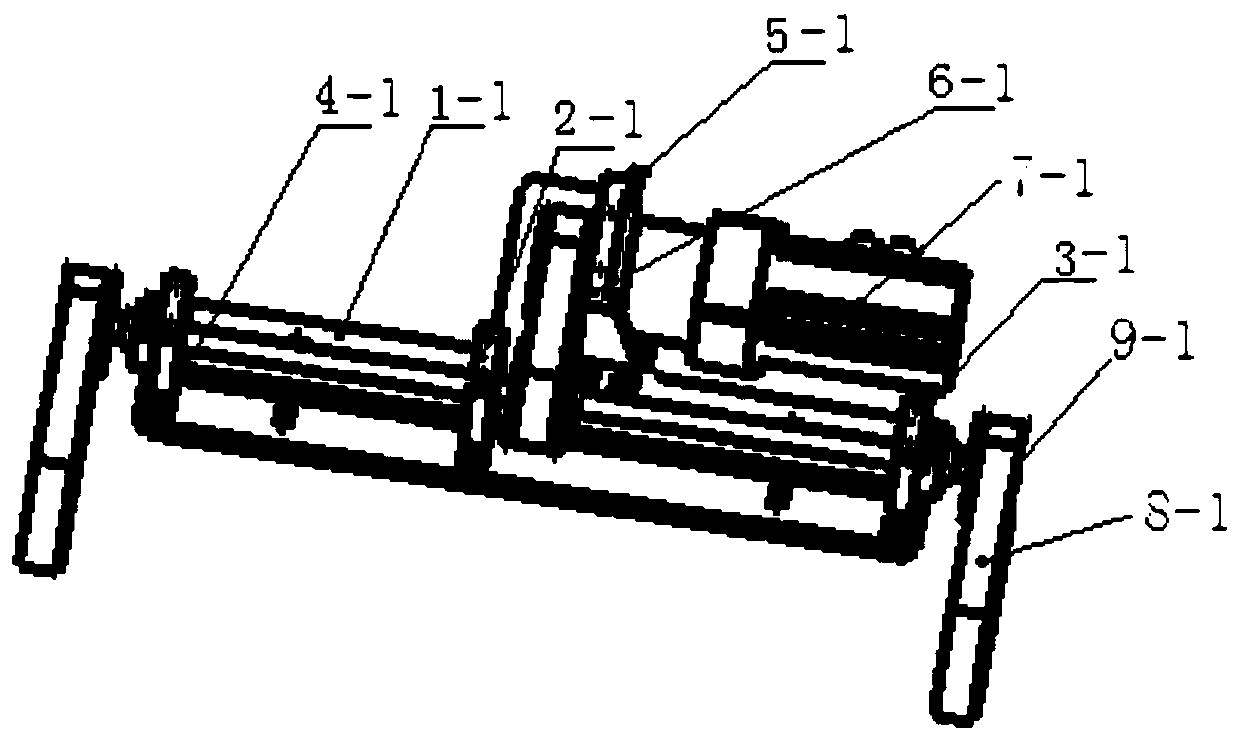
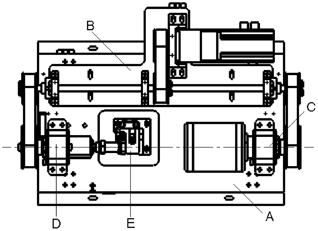
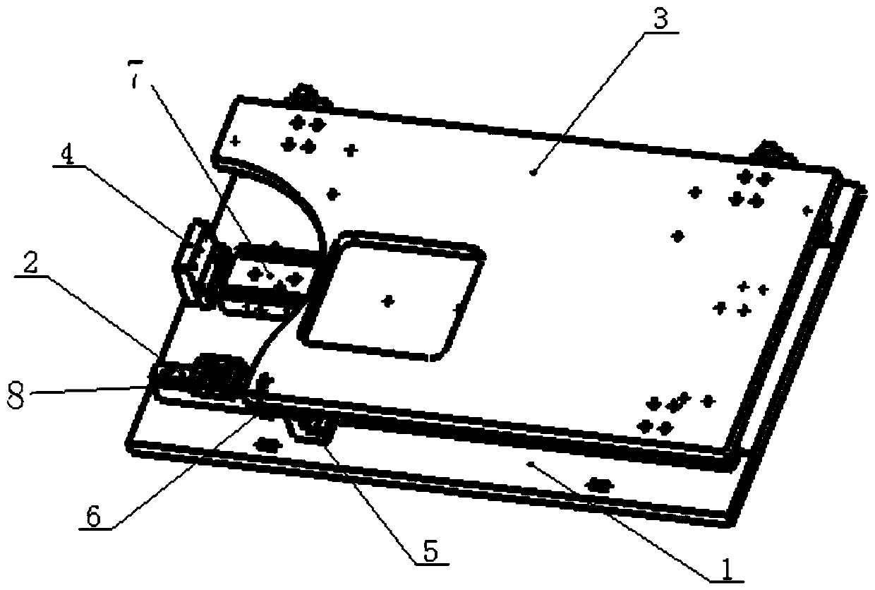
[0031] See attached Figure 1-10 , a sensor welding fixture of the present invention is composed of a base assembly, a motor rotating assembly, a wire-receiving follow-up assembly, a rotating assembly, and a support assembly, and the motor rotating assembly, the wire-receiving follow-up assembly, the rotating assembly, and the support assembly Installed on the base assembly respectively, the motor rotation assembly is respectively connected with the rotation assembly and the follow-up assembly through two pulleys, and the rotation assembly is connected with the support assembly; when the equipment is in operation, the motor rotation assembly is equipped with a photoelectric sensor, The photoelectric sensor is used as the initiator of the signal to ensure the consistency and stability of the welding of the workpiece during the welding p...


PUM


Abstract

The invention relates to a sensor welding fixture. The sensor welding fixture comprises a base component, an electrical machine rotating component, a wire winding servo component, a rotating componentand a rest component. The electrical machine rotating component, the wire winding servo component, the rotating component and the rest component are separately installed on the base component, the electrical machine rotating component is connected with the rotating component and the wire winding servo component through two belt pulleys, and the rotating component is connected with the rest component. The device has advantages of accurate positioning, reliable welding, high efficiency and zero disability rate.

Description

technical field [0001] The invention relates to a welding device, in particular to a sensor welding jig. Background technique [0002] The prior art includes manual welding, laser welding, etc. for the welding of sensors, but the welding efficiency is low, the labor intensity is low, the welding quality is low, the weld seam is not beautiful, and the scrap rate is high, which increases the production cost and reduces the production efficiency. Contents of the invention [0003] The object of the present invention is to provide a sensor welding jig, which has precise positioning, reliable welding, high efficiency and zero scrap rate. [0004] In order to achieve the above object, the present invention has the following technical solutions: [0005] A sensor welding jig of the present invention is composed of a base assembly, a motor rotation assembly, a wire take-up follow-up assembly, a rotation assembly, and a support assembly. The motor rotation assembly, the wire take-...

Claims


Application Information

Patent Timeline
Patent Type & Authority Patents(China)
IPC IPC(8): B23K26/21B23K26/70
CPCB23K26/21B23K26/702
Inventor 赵雷田杰赵章宏
Owner WUHAN CHUTIAN IND LASER EQUIP
Why Eureka
Try Eureka