
Rotor flux-based rotating speed calculation algorithm

A technology of rotor flux linkage and calculation algorithm, which is applied in the direction of electronically commutated motor control, generator control, control system, etc., can solve the problems of poor flux orientation accuracy, increased system hardware cost, and DC drift, etc., to achieve improved Accuracy, effect of improving observation results

Inactive Publication Date: 2018-08-17
UNIV OF SHANGHAI FOR SCI & TECH
View PDF3 Cites 2 Cited by
  • Summary
  • Abstract
  • Description
  • Claims
  • Application Information

AI Technical Summary

Problems solved by technology

Because the grid is a finishing accessory, it is easily invalidated by environmental factors during use, such as temperature, humidity and dust concentration, etc.
In addition, photoelectric encoders and rotary encoders have coaxial problems with the motor, and magnetic encoders are integrated components that have high requirements for environmental factors such as temperature.
In short, the increase of these devices will undoubtedly reduce the reliability of the system, lose the advantages of the asynchronous motor, such as simple structure and reliable operation, and increase the hardware cost of the system
[0004] In order to solve the problem of inconvenient installation and failure risk in the actual application of the speed sensor, engineers from foreign motor controller manufacturers conducted a speed sensorless test
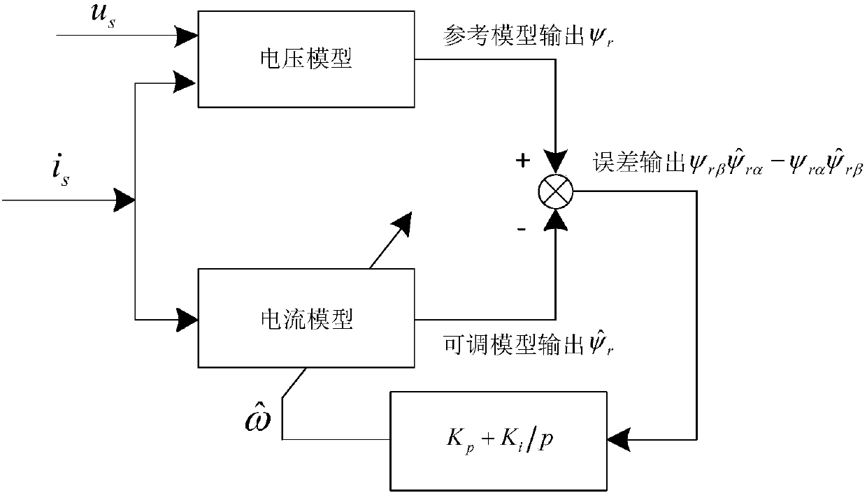
This technology aims at estimating the rotational speed through the motor mathematical model itself or establishing an observer to obtain the rotational speed information; when the MRAS method of the rotor flux linkage is used, the reference model of the MRAS method has a pure integral operation, which can lead to errors Problems such as accumulation and DC drift, and when the motor is running at low speed, the observed amplitude and phase errors make the accuracy of flux orientation worse

Method used


Image

  • Rotor flux-based rotating speed calculation algorithm
  • Rotor flux-based rotating speed calculation algorithm
  • Rotor flux-based rotating speed calculation algorithm

Examples


Embodiment Construction

[0025] In order to make the technical means, creative features, goals and effects of the present invention easy to understand, the following embodiments will specifically illustrate the rotor flux-linkage-based rotational speed calculation algorithm of the present invention in conjunction with the accompanying drawings.

[0026] figure 1 It is a schematic diagram of the improved current rotor flux linkage algorithm in the embodiment of the present invention.

[0027] The calculation algorithm of the rotational speed based on the rotor flux linkage in this embodiment includes the following steps:

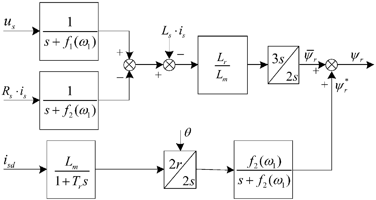
[0028] Step 1: After calculating the stator voltage, the product of stator resistance and stator current, and the stator inductance L s Stator inductance i s The product is subtracted to obtain the calculated value of the rotor flux linkage on the stationary two-phase coordinates.

[0029]

[0030] ψ r is the rotor flux linkage, u s is the stator voltage vector, i s is the s...


PUM


Abstract

The invention provides a rotor flux-based rotating speed calculation algorithm for improving the orientation accuracy of a rotor. The rotating speed calculation algorithm provided by the invention comprises the following steps of (1) calculating a product of stator voltage, stator resistance and stator current and then making a difference from the product of stator inductance Ls and stator inductance is to obtain a rotor flux calculated value in a two-phase static coordinate; (2) substituting the real-time adjusted cutoff frequency into a compensation amount calculation formula and taking theobtained numerical value as a compensated flux value; (3) calculating a current rotor flux value under current exciting current according to the rotor flux calculated value and the compensated flux value; (4) calculating an adjustable rotor flux value according to alpha and beta-axis components of the rotor flux, the stator resistance, rotor inductance and mutual inductance, the stator inductanceand a differential operator; and (5) calculating a rotating speed of the motor according to the current rotor flux value and the adjustable rotor flux value.

Description

technical field [0001] The invention specifically relates to a rotational speed calculation algorithm based on rotor flux linkage. Background technique [0002] With the introduction and promotion of modern AC speed control theory and the development of power electronic devices, the AC power drive system with asynchronous motors and synchronous motors as the main control objects has gradually changed from non-adjustable speed to adjustable speed and even high-precision. The transition in the direction of rapid development, and more and more attention to energy-saving issues such as system energy utilization. High-performance speed regulation has become the development trend of AC electric drive system. In order to achieve the purpose of precise speed regulation and energy saving, closed-loop control of the motor speed is required. For this purpose, it is necessary to obtain real-time speed information of the motor, such as fans and water pump systems with general-purpose in...

Claims


Application Information

Patent Timeline
IPC IPC(8): H02P21/14H02P21/18H02P21/24
CPCH02P21/14H02P21/18H02P21/24
Inventor 金爱娟唐新雯杨晓洁周敏李少龙
Owner UNIV OF SHANGHAI FOR SCI & TECH
Learn More