A fuel cell guide plate, fuel cell stack and system

A fuel cell stack and deflector plate technology, applied to fuel cells, fuel cell components, circuits, etc., can solve problems such as air waste, reduced fuel cell system efficiency, and increased mechanical power consumption for air delivery or hydrogen circulation

Inactive Publication Date: 2020-09-18
上海氢尚新能源科技有限公司
View PDF1 Cites 0 Cited by
  • Summary
  • Abstract
  • Description
  • Claims
  • Application Information

AI Technical Summary

Problems solved by technology

[0005] This design is to design more fluid inlets and outlets, and design the diversion groove as a straight-flow groove or a near-flow groove as much as possible. Compared with the traditional serpentine flow path, it does reduce the situation of water blocking. Due to the limitation of the size of the flow plate, the design of this straight channel makes hydrogen and air be discharged from the stack before they can react, a large amount of air is wasted or excess hydrogen is circulated, which will inevitably cause the mechanical work of transporting air or circulating hydrogen. consumption increases, thereby reducing the efficiency of the fuel cell system

Method used


Image

  • A fuel cell guide plate, fuel cell stack and system
  • A fuel cell guide plate, fuel cell stack and system

Examples


Embodiment 1

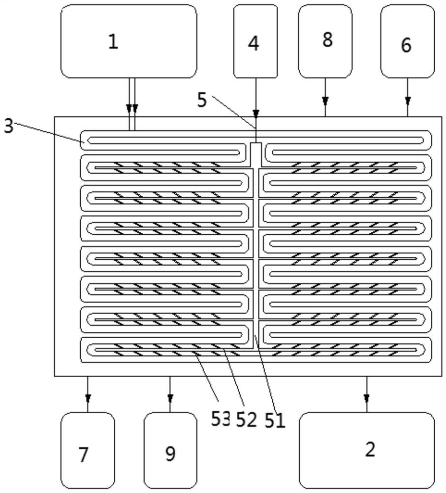
[0029] like figure 1 As shown, the fuel cell guide plate is a conventional fuel cell guide plate, which consists of a front guide air channel plate, a reverse hydrogen guide air flow channel plate, and a middle cooling fluid interlayer, wherein the front guide An oxidant fluid inlet 1 and an oxidant fluid outlet 2 are arranged on the air flow groove plate, and the oxidant fluid inlet 1 and the oxidant fluid outlet 2 are connected through the oxidant main channel 3, the fuel inlet 6, the fuel outlet 7, the cooling fluid inlet 8, the cooling fluid Fluid outlet 9, wherein the reverse hydrogen guide flow channel plate is provided with a fuel guide groove connecting the fuel inlet 6 and the fuel outlet 7, and the middle guide cooling fluid interlayer is provided with a cooling fluid guide connecting the cooling fluid inlet 8 and the cooling fluid outlet 9 groove.

[0030]Add oxidant auxiliary inlet 4 and oxidant auxiliary flow channel 5 on the front guide air flow channel plate of...

Embodiment 2

[0036] The width of the microgrooves 52 is 1 / 2 of the width of the oxidant main channel 3 . The width of the capillary groove 53 is 1 / 3 of the width of the oxidant main channel 3 . The output pressure of the auxiliary oxidant compressor 14 is five times that of the main oxidant compressor 11 . All the other are with embodiment 1.

Embodiment 3

[0038] The width of the microgrooves 52 is 1 / 10 of the width of the oxidant main channel 3 . The width of the capillary groove 53 is 1 / 20 of the width of the oxidant main channel 3 . The output pressure of the auxiliary oxidant compressor 14 is twice that of the main oxidant compressor 11 . All the other are with embodiment 1.


PUM


Abstract

The invention belongs to the technical field of a fuel cell, and relates to a fuel cell flow guiding polar plate and a fuel cell stack and system. Two oxidant inlets and two oxidant flowing channels are formed in the flow guiding polar plate; the two oxidant flowing channels are connected with the two oxidant inlets respectively for conveying oxidant to each oxidant flowing channel through the twooxidant inlets; the fuel cell stack adopts the abovementioned flow guiding polar plate; and a fuel cell power generation system also comprises two independent oxidant supply systems, and comprises two independent compressors, and adjusts the fluid flows and pressure in the two paths of the oxidant flowing channels. Compared with the prior art, by virtue of the flow guiding polar plate provided bythe invention, fluids in the flowing channels and a ventilating layer can be conveyed and drained more smoothly with higher efficiency, without causing a phenomenon of water blocking.

Description

technical field [0001] The invention belongs to the technical field of fuel cells, and specifically proposes a new fuel cell guide plate, a fuel cell stack and a system. Background technique [0002] A fuel cell is a device that directly converts the chemical energy of hydrogen and oxygen into electrical energy through an electrode reaction. A fuel cell is generally constructed of a plurality of cells, each cell comprising two electrodes (anode and cathode) separated by an electrolyte element and assembled in series with each other to form a fuel cell stack. The electrochemical reaction is achieved by supplying the appropriate reactants to each electrode, ie fuel to one electrode and oxidant to the other, creating a potential difference between the electrodes and thereby generating electrical energy. [0003] In order to supply each electrode with reactants, specific interface elements commonly referred to as "bipolar plates" and arranged on both sides of each individual ce...

Claims


Application Information

Patent Timeline
Patent Type & Authority Patents(China)
IPC IPC(8): H01M8/026H01M8/0263
CPCH01M8/026H01M8/0263Y02E60/50
Inventor 高勇
Owner 上海氢尚新能源科技有限公司
Why Eureka
Try Eureka