
Weld leg component, arrayed weld leg module and key component

A technology of components and solder feet, which is applied in the field of button components, can solve the problems of complex manufacturing process of conductive buttons of solder feet, increase the production cost of conductive buttons, and difficult to control the coplanarity of solder feet, so as to improve product competitiveness, The effect of increasing the difficulty of the manufacturing process and improving the reliability of the product

Pending Publication Date: 2018-08-17
GUILIN UNIV OF ELECTRONIC TECH +1
View PDF0 Cites 1 Cited by
  • Summary
  • Abstract
  • Description
  • Claims
  • Application Information

AI Technical Summary

Problems solved by technology

[0002] The conductive button is one of many electronic product accessories. Its main function is to connect the conductive sheet to the contact to achieve the purpose of conduction. When the conductive button is pressed, the conductive sheet inside the button can be connected to the contact to form an electrical connection. , but in the existing conductive button preparation process, the manufacturing process of the conductive button with solder feet is complicated, and the coplanarity of the solder feet is difficult to control, which directly increases the production cost and reduces the performance of the conductive button

Method used


Image

  • Weld leg component, arrayed weld leg module and key component
  • Weld leg component, arrayed weld leg module and key component
  • Weld leg component, arrayed weld leg module and key component

Examples


Embodiment Construction

[0043] In order to understand the above-mentioned purpose, features and advantages of the present invention more clearly, the present invention will be further described in detail below in conjunction with the accompanying drawings and specific embodiments. It should be noted that, in the case of no conflict, the embodiments of the present application and the features in the embodiments can be combined with each other.

[0044] In the following description, many specific details are set forth in order to fully understand the present invention. However, the present invention can also be implemented in other ways different from those described here. Therefore, the protection scope of the present invention is not limited by the specific details disclosed below. EXAMPLE LIMITATIONS.

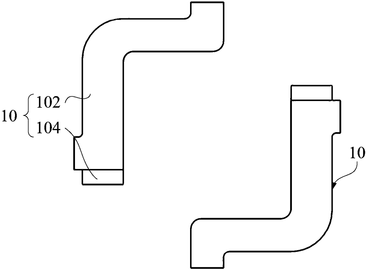
[0045] Refer below Figure 1 to Figure 7 Describe the solder pin assembly 10 , the array solder pin module 6 and the button assembly 5 according to some embodiments of the present invention.

[004...


PUM


Abstract

The invention provides a weld leg component, an arrayed weld leg module and a key component. The key component includes a base. The weld leg component includes a support and weld leg, wherein the support is connected with the base; one end of the weld leg is connected with the support, and the other end of the weld leg is bent away from the base and extended below the support; the weld leg and thesupport are at least partially overlapped relative to the projection of the base; the support can support the weld leg; chances for the weld leg to deform are slimmed; weld leg coplanarity is effectively ensured at the premise of not greatly increasing the manufacture difficulty; key component fitting effect is improved.

Description

technical field [0001] The invention relates to the technical field of keys, in particular to a solder leg assembly, an array solder leg module and a key assembly. Background technique [0002] The conductive button is one of many electronic product accessories. Its main function is to connect the conductive sheet to the contact to achieve the purpose of conduction. When the conductive button is pressed, the conductive sheet inside the button can be connected to the contact to form an electrical connection. , but in the existing manufacturing process of conductive buttons, the manufacturing process of conductive buttons with solder feet is complicated, and the coplanarity of solder feet is difficult to control, which directly increases the production cost and reduces the performance of conductive buttons. Contents of the invention [0003] The present invention aims to solve at least one of the technical problems existing in the prior art or related art. [0004] Therefor...

Claims


Application Information

Patent Timeline
IPC IPC(8): H01H13/10H01H13/26
CPCH01H13/10H01H13/26
Inventor 蔡苗梁永湖杨道国郑建娜陈宣佑
Owner GUILIN UNIV OF ELECTRONIC TECH
Learn More