
Method for nondestructively detecting asphalt pavement crack conditions

A technology for asphalt pavement and non-destructive testing, which is applied in the direction of measuring devices, instruments, scientific instruments, etc., can solve the problems of expensive equipment, core sample removal, and low precision, and achieve the effects of simple operation, low cost and accurate test results

Active Publication Date: 2018-08-17
KUNSHAN CONSTRUCT ENG QUALITY TESTING CENT +1
View PDF3 Cites 3 Cited by
  • Summary
  • Abstract
  • Description
  • Claims
  • Application Information

AI Technical Summary

Problems solved by technology

At present, in order to grasp the cracking status of asphalt pavement cracks, especially the depth of cracks extending downward, the commonly used method is core sampling, a damage detection method, that is, cores are taken across the cracks, and the status of the cracks is judged by the core samples. Pavement crack condition, although this method is intuitive, it is a destructive detection method; in addition, for deeper cracks, core samples may not be taken out completely
Some studies have also proposed the use of ground-penetrating radar technology to detect pavement cracks. This technology can theoretically achieve non-destructive testing, but the equipment is expensive and the accuracy is low.

Method used


Image

  • Method for nondestructively detecting asphalt pavement crack conditions
  • Method for nondestructively detecting asphalt pavement crack conditions
  • Method for nondestructively detecting asphalt pavement crack conditions

Examples


Embodiment Construction

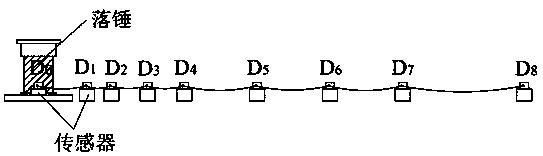
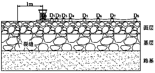
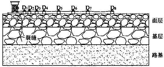
[0018] In order to solve the defects of high implementation cost, low detection accuracy and complicated operation existing in the existing non-destructive testing technology, the idea of ​​the present invention is to use the drop weight deflection instrument to realize the accurate detection of the downward extension of asphalt pavement cracks. and non-destructive testing.

[0019] The Falling Weight Deflectormeter (FWD for short) was produced in the early 1970s. It is a pulse dynamic deflector. It simulates the instantaneous impact of the vehicle load on the road surface to obtain the instantaneous deformation of the road surface. The measurement results are more accurate and have a large amount of information. Its working principle is: under the control of the computer, the weight of a certain mass is lifted to a certain height by the hydraulic transmission device and then falls freely. The impact force acts on the bearing plate and is transmitted to the road surface, there...


PUM


Abstract

The invention discloses a method for nondestructively detecting asphalt pavement crack conditions. The method includes steps of 1, measuring difference delta L1 of deflection values of first measuredpoints and second measured points by the aid of falling weight deflectometers; 2, shifting corresponding load application points to the other side of each crack and measuring difference delta L2 of deflection values of third measured points and fourth measured points by the aid of the falling weight deflectometers; 3, judging the asphalt pavement crack conditions according to an equation of deltaL=delta L2-delta L1. The distance from each load application point to the corresponding crack is a preset distance constant value, each load application point, the corresponding first measured point and the corresponding second measured point are positioned on the same side of the corresponding crack, and the distance from each load application point to the corresponding crack, the distance from the corresponding first measured point to the corresponding crack and the distance from the corresponding second measured point to the corresponding crack are sequentially enlarged. The locations of the third measured points / the fourth measured points relative to the load application points are identical to the locations of the first measured points / the second measured points at the step 1 relativeto the load application points, and the cracks are positioned on the center lines between the third measured points and the fourth measured points. The method has the advantages that the asphalt pavement crack conditions can be nondestructively detected by the aid of the method so as to be accurately evaluated; the method is easy and convenient to operate and extremely low in implementation cost.

Description

technical field [0001] The invention relates to a non-destructive detection method for the crack condition of asphalt pavement, which belongs to the technical field of detection of asphalt pavement defects. Background technique [0002] Cracks are one of the most typical diseases of asphalt pavement. Asphalt pavement is a layered system structure, the visible cracks on the pavement surface may only occur in the asphalt concrete surface layer, or may occur in the asphalt concrete surface layer and semi-rigid base layer, and may also occur in the asphalt concrete surface layer, On the semi-rigid base and subgrade, it is obvious that the different conditions of pavement cracking and cracking are closely related to the maintenance and repair plan of cracks. At present, in order to grasp the cracking status of asphalt pavement cracks, especially the depth of cracks extending downward, the commonly used method is core sampling, a damage detection method, that is, cores are taken ...

Claims


Application Information

Patent Timeline
IPC IPC(8): G01N3/303
CPCG01N3/303G01N2203/001G01N2203/0039G01N2203/0066
Inventor 沈美荣马翔张美颖彭骏亚钱晓刚田缘
Owner KUNSHAN CONSTRUCT ENG QUALITY TESTING CENT
Learn More