
Preignition detection method for internal combustion engine

A detection method and internal combustion engine technology, applied in the direction of internal combustion engine testing, etc., can solve the problems of low signal response speed of cooling water temperature sensor, ineffective real-time monitoring of abnormal combustion, failure of early combustion detection of anti-knock fuel, etc., and achieve high speed correction accuracy and good performance Application prospects in the real vehicle environment and the effect of low cost

Active Publication Date: 2018-08-17
TSINGHUA UNIV
View PDF5 Cites 4 Cited by
  • Summary
  • Abstract
  • Description
  • Claims
  • Application Information

AI Technical Summary

Problems solved by technology

[0004] However, the algorithm of the existing pre-ignition diagnosis method is relatively complicated or the practicability is poor.
Due to the limitations of cost, product design, and sensor layout space in the real vehicle environment, pre-ignition diagnosis can only be performed based on existing on-board sensors, such as knock sensors, cooling water temperature sensors, 58-tooth speed sensors, etc., but knock sensors are anti-knock Pre-ignition detection of fuels (such as methanol, ethanol, natural gas) fails, and the signal response speed of the cooling water temperature sensor is low, which cannot effectively monitor abnormal combustion in real time

Method used


Image

  • Preignition detection method for internal combustion engine
  • Preignition detection method for internal combustion engine
  • Preignition detection method for internal combustion engine

Examples


Embodiment 1

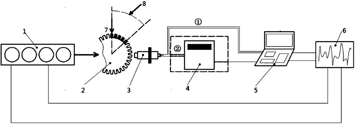
[0046] This embodiment provides a method for detecting pre-ignition of an internal combustion engine, and the layout of the detection device is as follows figure 1As shown, the original signal of the instantaneous speed of the flywheel ring gear 2 in the internal combustion engine 1 is first obtained through the 58-tooth speed sensor 3, and then the original signal of the instantaneous speed is preprocessed to obtain the instantaneous speed containing abnormal combustion information, and then the instantaneous speed Perform first-order derivation to obtain the instantaneous angular acceleration, extract all the instantaneous angular accelerations in the feature window 8, and integrate to obtain the integral value, compare the integral value with the pre-ignition threshold of the detection window to determine whether it is pre-ignition, the algorithm Integrated in ECU5, if pre-ignition occurs, control strategy 6 is adopted to feed back to internal combustion engine 1;

[0047] ...


PUM


Abstract

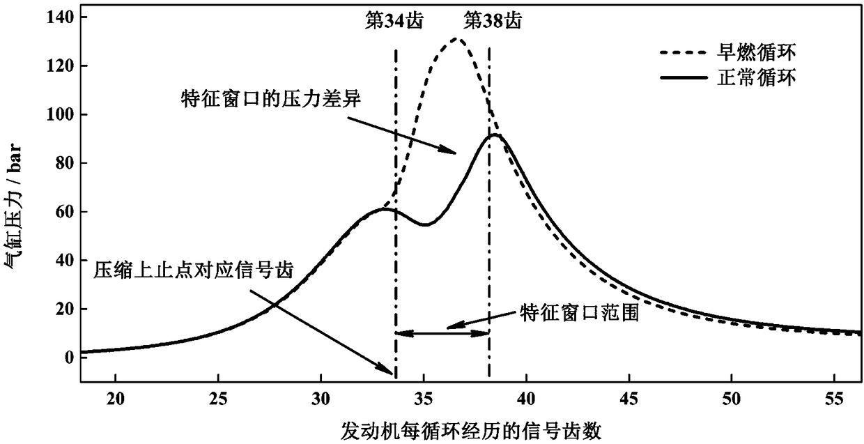
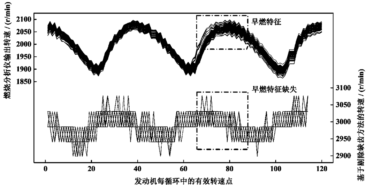
The invention relates to a preignition detection method for an internal combustion engine. The method comprises the steps that all instantaneous angular accelerations in a feature window are integrated to acquire an integral value, and whether the internal combustion engine is pre-ignited according to the integral value and a preignition threshold in a detection window; the feature window is an angular range corresponding to the compression top dead center of the internal combustion engine and continuous 3 to 5 signal teeth behind the compression top dead center along the rotation direction ofa crankshaft; and the instantaneous angular accelerations correspond to the signal teeth in the feature window one to one. According to the invention, the preignition detection method has the advantages of simple algorithm and small calculation amount; 3 to 5 data of the feature window are numerically integrated; abnormal combustion is not judged by cylinder pressure reconstruction through complicated time-frequency analysis and vibration information; changing the structure of the internal combustion engine is not needed; the marketization cycle is short; a 58-tooth rotation speed sensor is one of the basic configurations of the internal combustion engine; the method does not need any additional device, so that the cost is low; the detection accuracy is high for both steady state and transient conditions; and the method has a good application prospect in a real vehicle environment.

Description

technical field [0001] The invention relates to the field of combustion diagnosis and control of internal combustion engines, and more specifically, to a detection method for early combustion of internal combustion engines. Background technique [0002] Internal combustion engines are the dominant power for vehicles, ships, construction machinery and defense equipment. Pre-ignition is an important cause of conventional knock and super-knock of internal combustion engines. Once continuous pre-combustion occurs, the internal combustion engine is very likely to be damaged. There are two main causes of pre-ignition: 1) structural hotspots; 2) non-structural hotspots. Structural hotspots mainly refer to the protruding structures in the combustion chamber that form heat cusps during the combustion process in the cylinder, which become fixed ignition sources. Structural hotspots are mainly controlled by optimizing the combustion system structure, strengthening local cooling, and r...

Claims


Application Information

Patent Timeline
Patent Type & Authority Applications(China)
IPC IPC(8): G01M15/05
CPCG01M15/05
Inventor 范钦灏王志齐运亮
Owner TSINGHUA UNIV
Learn More