Alternative grouting method for steel-structure column feet

A steel structure and column foot technology, applied in the direction of columns, pier columns, pillars, etc., can solve the problems that affect the safety of the structure, the load is large, and the inability to fill densely, etc., to achieve the effect of stable structure and densely poured

Active Publication Date: 2018-08-17
CHINA CONSTR EIGHT ENG DIV CORP LTD
View PDF4 Cites 1 Cited by
  • Summary
  • Abstract
  • Description
  • Claims
  • Application Information

AI Technical Summary

Problems solved by technology

Due to the heavy load on the upper part of many steel structures, it is not allowed to reserve grouting holes or open holes on the horizontal steel plate at the base of the column. The grouting can only be injected from the side gaps, resulting in the inability to be densely grouted and affecting the safety of the structure.

Method used


Image

  • Alternative grouting method for steel-structure column feet
  • Alternative grouting method for steel-structure column feet
  • Alternative grouting method for steel-structure column feet

Examples


Embodiment Construction

[0026] In order to provide a more compact grouting method for steel structure column feet and ensure a more stable and safe structure, the present invention provides an alternate grouting method for steel structure column feet.

[0027] The preferred embodiment of the steel structure column base alternate grouting method of the present invention will be further described below in conjunction with the accompanying drawings and specific embodiments. Those skilled in the art can easily understand other advantages and effects of the present invention from the contents disclosed in this specification.

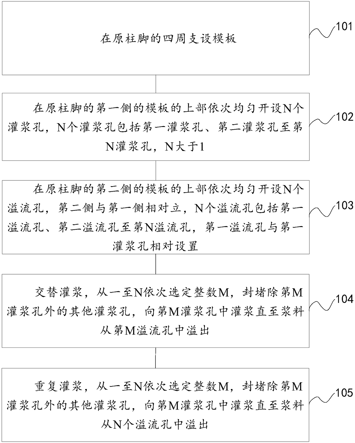
[0028] combine figure 1 As shown, the alternate grouting method for steel structure column feet of the present invention comprises steps:

[0029] Step 101: supporting formwork around the original column foot;

[0030] Step 102: Open N grouting holes evenly in sequence on the upper part of the formwork on the first side of the original column base, and the N grouting holes include...


PUM


Abstract

The invention discloses an alternative grouting method for steel-structure column feet. The alternative grouting method comprises the following steps: arranging a template; sequentially and uniformlyforming N grouting holes in the upper part of the template at the first side of the original column feet, wherein N grouting holes comprise first grouting hole to N-th grouting holes, and N is greaterthan 1; sequentially and uniformly forming N overflow holes in the upper part of the template at the second side of the original column feet, wherein the N overflow holes comprise first overflow holeto N-th overflow hole, and the first overflow hole and the first grouting hole are oppositely formed; alternatively grouting, selecting an integer M from one to N sequentially, sealing other groutingholes except from the M-th grouting hole, grouting the M-th grouting hole until slurry overflows from the M-th overflow hole; repeatedly grouting, selecting the integer M from one to N sequentially,sealing other grouting holes except from the M-th grouting hole, grouting the M-th grouting hole until the slurry overflows from the N-th overflow hole. The alternative grouting method is used to sequentially grout the grouting holes until the corresponding overflow holes overflow, so that the grouting is more compact. The more stable and safer structure is guaranteed.

Description

technical field [0001] The invention relates to the field of building construction, in particular to a grouting method for steel structure column feet. Background technique [0002] Steel structure construction often has a column base grouting process. After the steel structure column base is installed and the bolts are fixed, gaps are reserved at the bottom, and the gaps are sealed and compacted with high-strength non-shrinkage grouting materials. Due to the heavy load on the upper part of many steel structures, it is not allowed to reserve grouting holes or open holes on the horizontal steel plate at the base of the column. The grouting can only be injected from the side gaps, resulting in the inability to be densely grouted and affecting the safety of the structure. [0003] For this reason, it is necessary to provide a more compact steel structure column foot grouting method to ensure that the structure is more stable and safe. Contents of the invention [0004] In or...

Claims


Application Information

Patent Timeline
Patent Type & Authority Applications(China)
IPC IPC(8): E04C3/32E04G21/00
CPCE04C3/32E04G21/00
Inventor 李维强郑洪邓磊王保栋李宝泉祝金龙
Owner CHINA CONSTR EIGHT ENG DIV CORP LTD
Why Eureka
Try Eureka