
Gas buoyancy auxiliary welding device and welding method utilizing same

An auxiliary welding and buoyancy technology, applied in welding equipment, laser welding equipment, metal processing equipment, etc., can solve the problems of unbalanced surface tension, poor weld quality, and affecting welding applications, etc., to achieve simple structure and improve welding quality , Eliminate the effect of collapse

Active Publication Date: 2018-08-17
HUNAN UNIV
View PDF9 Cites 9 Cited by
  • Summary
  • Abstract
  • Description
  • Claims
  • Application Information

AI Technical Summary

Problems solved by technology

[0004] In order to achieve the above-mentioned problems when the welding thickness increases, the gravity on the lower surface of the molten pool increases, and its surface tension cannot balance the gravity, resulting in welding defects such as molten pool collapse, bottom humps, etc., resulting in poor weld quality and affecting welding applications.

Method used


Image

  • Gas buoyancy auxiliary welding device and welding method utilizing same
  • Gas buoyancy auxiliary welding device and welding method utilizing same
  • Gas buoyancy auxiliary welding device and welding method utilizing same

Examples


example 1

[0067] The morphology of the weld seam on the upper and lower surfaces of 316L stainless steel with a thickness of 16mm was tested and observed. The adopted process parameters were laser power 16kW and welding speed 0.65m / min. The gravity on the surface is:

[0068] p h =ρg 0 h=7.98×9.8×16≈1.3kPa

[0069] Among them, ρ is the density of 316L stainless steel liquid, g 0 is the gravity coefficient, about 9.8m / s 2 , h is the thickness of the specimen.

[0070] Such as Figure 5 The picture shown shows the topography of the weld seam (a) and the bottom surface of the weld seam (b) without air pressure support. The weld seam cutting marks on the top surface are very obvious, while the weld seam on the bottom surface is wider , Welding quality is extremely poor. Such as Image 6 The figure shown shows the topography (a) of the upper surface of the welding seam and the topography (b) of the bottom surface of the welding seam of the thick plate with air support. Compared with ...

example 2

[0072] The morphology of the weld seam on the upper and lower surfaces of 20mm thick 316LN stainless steel was tested and observed. The adopted process parameters were laser power 16kW and welding speed 0.80m / min. During the welding process, for the specimen 2 used in this test, the lower surface of the molten pool The gravitational force is:

[0073] p h =ρg 0 h=7.98×9.8×20≈1.6kPa

[0074] Among them, ρ is the density of 316LN stainless steel liquid, g 0 is the gravity coefficient, about 9.8m / s 2 , h is the thickness of the specimen.

[0075] Such as Figure 7 The figure shown in the figure shows the topography (a) of the upper surface of the welding seam and the topography (b) of the lower surface of the welding seam without air pressure support. It can be seen that the upper surface of the weld has serious subsidence and the lower surface has a huge Hump, poor solder quality. Such as Figure 8 The figure shown shows the topography (a) of the upper surface of the wel...


PUM


Abstract

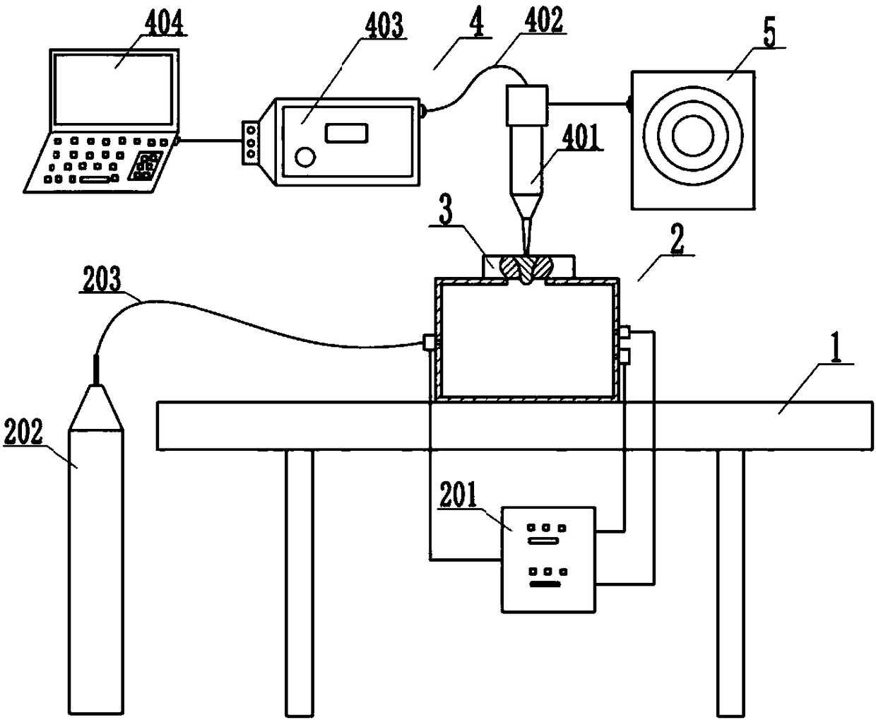
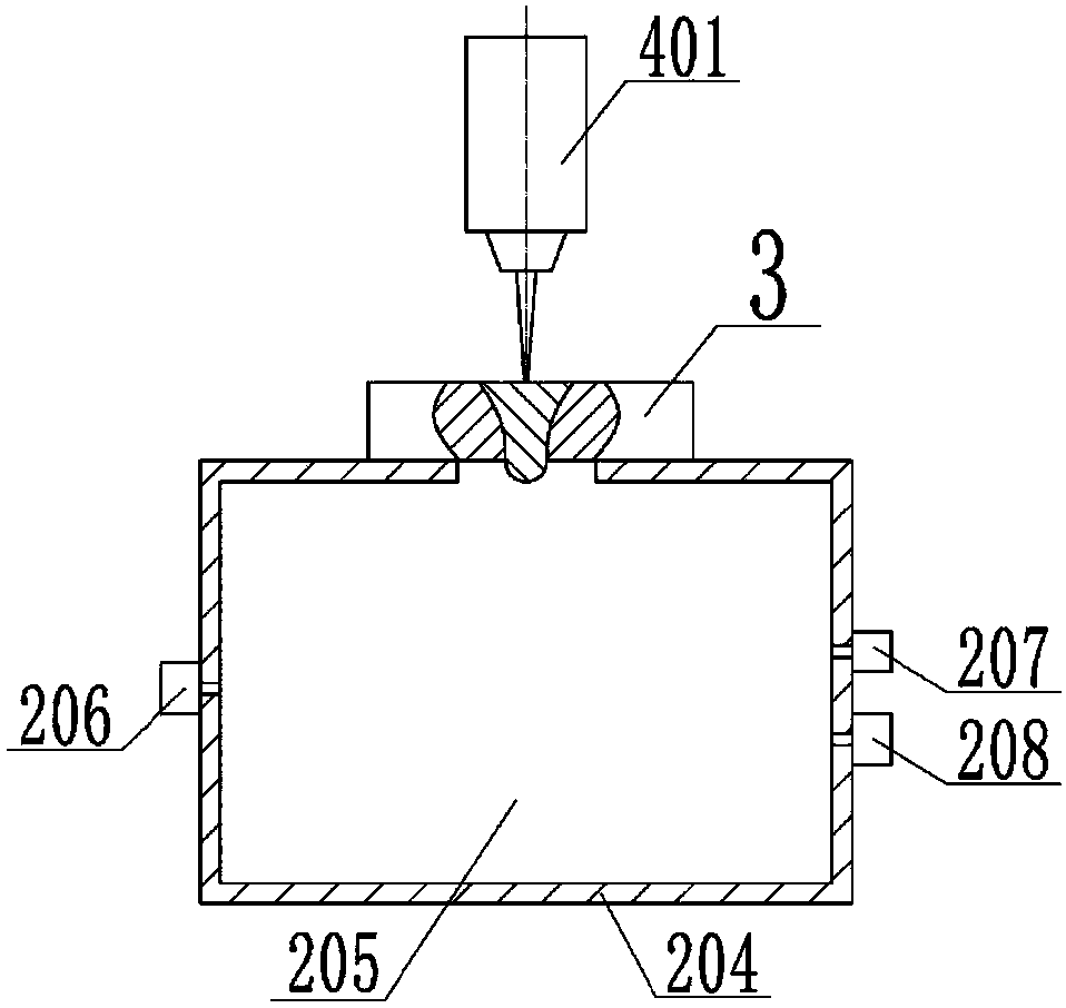
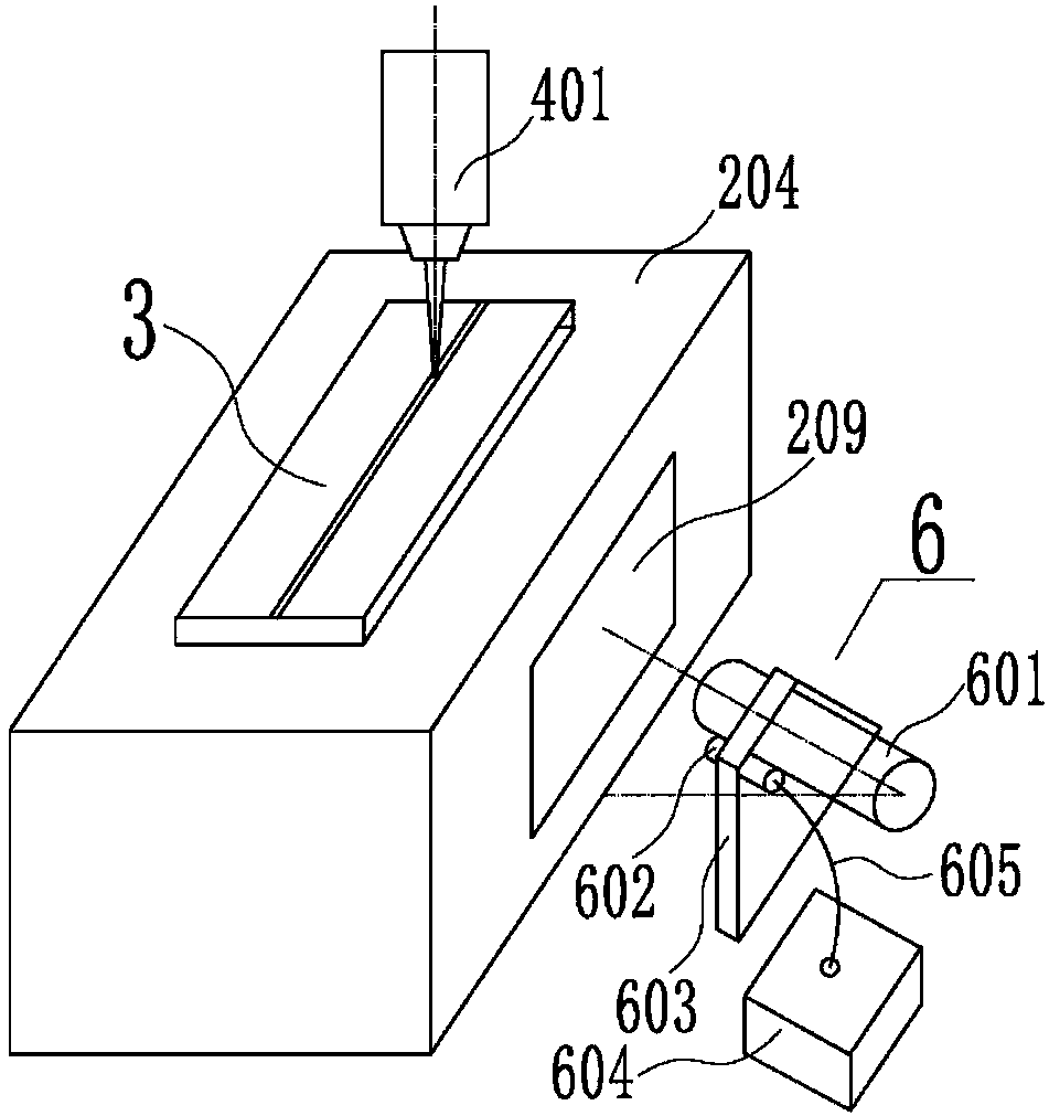
The invention provides a gas buoyancy auxiliary welding device. The gas buoyancy auxiliary welding device comprises a welding platform (1) and a gas pressure supporting device (2). The gas buoyancy auxiliary welding device is characterized in that in the welding process, a gas pressure controller (201) in a gas chamber (205) continuously reads the value of the gas pressure in the gas chamber through a gas pressure sensor (207), the read gas pressure value is compared with a target gas pressure value, and accordingly, the gas pressure in the gas chamber keeps stable by controlling the flow rateof a gas outlet solenoid valve (206) and a gas inlet solenoid valve (208). According to the gas buoyancy auxiliary welding device, the pressure of gas under welding seams counteracts the gravity borne by a welding pool, thus, collapse, humps and other welding defects are eliminated, the welding quality is improved, the welding thickness of a laser device is increased, and the gas buoyancy auxiliary welding device is simple in structure and easy to apply and popularize.

Description

technical field [0001] The invention relates to a welding technology, in particular to a gas buoyancy auxiliary welding device and a welding method using the device. Background technique [0002] Laser welding is an important field of application of laser technology. It has the advantages of small heat input, high welding precision, low residual stress, large aspect ratio, and easy automatic control. It has been widely developed and applied, especially in the field of welding difficult-to-weld materials and special structures. Manufacturing fields such as aviation, aerospace, automobiles, shipbuilding, electronics, and nuclear power have received great attention from all countries in the world. With the development of laser technology, the power that lasers can achieve is getting higher and higher, and the thickness that can be welded by a single laser is also increasing. However, as the welding thickness increases, the gravity on the lower surface of the molten pool also ...

Claims


Application Information

Patent Timeline
Patent Type & Authority Applications(China)
IPC IPC(8): B23K26/70B23K26/06B23K26/21B23K26/348
CPCB23K26/06B23K26/21B23K26/348B23K26/702
Inventor 陈根余陈飞
Owner HUNAN UNIV
Learn More