
Visual monitoring method and system for heat supply network data of heating station heat supply area

A heat station and heating pipe network technology, applied in other database browsing/visualization, data processing applications, other database retrieval, etc., can solve unfavorable energy saving and emission reduction, difficulty in achieving the best operating state of the heating system, and affecting heating Service quality and other issues to achieve the effect of improving management level and production efficiency, providing heating service quality, and facilitating unified distribution

Pending Publication Date: 2018-08-14
北明天时能源科技(北京)有限公司
View PDF4 Cites 8 Cited by
  • Summary
  • Abstract
  • Description
  • Claims
  • Application Information

AI Technical Summary

Problems solved by technology

At present, thermal systems, such as heat exchange stations, mostly use manual monitoring. Manual monitoring is not only a waste of manpower; it is also difficult for operators to find hidden dangers of accidents, which may easily cause equipment accidents.
At the same time, each heat exchange station is relatively scattered and operates independently, which makes it difficult to achieve the best operating state of the heating system as a whole, resulting in a thermal imbalance of the entire heating network, affecting the heating effect and causing a great waste of energy, which is very unfavorable for energy saving and emission reduction. , and even affect the quality of heating service

Method used


Image

  • Visual monitoring method and system for heat supply network data of heating station heat supply area
  • Visual monitoring method and system for heat supply network data of heating station heat supply area

Examples


Embodiment Construction

[0040] Exemplary embodiments of the present disclosure will be described in more detail below with reference to the accompanying drawings. Although exemplary embodiments of the present disclosure are shown in the drawings, it should be understood that the present disclosure may be embodied in various forms and should not be limited by the embodiments set forth herein. Rather, these embodiments are provided for more thorough understanding of the present disclosure and to fully convey the scope of the present disclosure to those skilled in the art.

[0041] Those skilled in the art can understand that, unless otherwise defined, all terms (including technical terms and scientific terms) used herein have the same meaning as commonly understood by those of ordinary skill in the art to which this invention belongs. It should also be understood that terms, such as those defined in commonly used dictionaries, should be understood to have meanings consistent with the meanings in the co...


PUM


Abstract

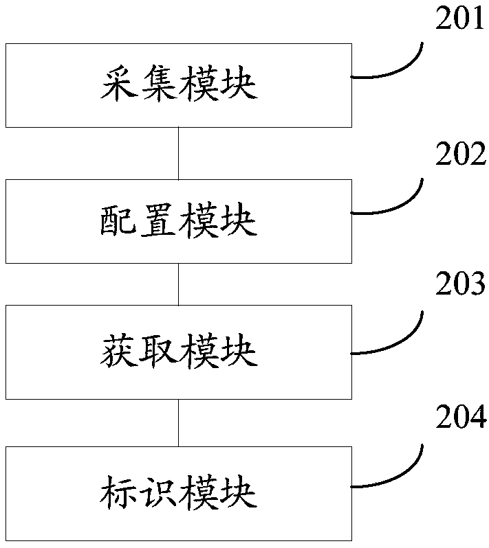
The invention provides a visual monitoring method and system for the heat supply network data of a heating station heat supply area. The method comprises the following steps that: collecting the monitoring data of the fixing monitoring point of a heat-supply pipe network in each heating station heat supply area in an appointed area; taking each piece of collected monitoring data as the heat supplynetwork data of the corresponding heating station heat supply area; according to a preset first mapping relationship, obtaining an identification color corresponding to the heat supply network data of each heating station heat supply area, wherein the first mapping relationship comprises a corresponding relationship between the numerical value range of the heat supply network data and the identification color; and according to the obtained identification color, independently identifying the corresponding boundary graph of each heating station heat supply area in a heat supply heat supply network graph. By use of the method, management personnel can conveniently and visually know the working condition of the heat supply network and carry out regulation and control according to the workingcondition of the heat supply network, energy waste is reduced so as to be favorable for energy saving and emission reduction, in addition, the comprehensive monitoring of a thermodynamic system is realized, and therefore, heat supply service quality is favorably provided.

Description

technical field [0001] The invention relates to the technical field of heating network data monitoring, in particular to a method and system for visual monitoring of heating network data in a heating area of ​​a thermal station. Background technique [0002] With the rapid development of the national economy, the scale of my country's urban centralized heating is also expanding, and scientific management of the heat pipe network has very significant economic and social benefits. At present, thermal systems, such as heat exchange stations, mostly use manual monitoring. Manual monitoring is not only a waste of manpower; it is also difficult for operators to find hidden dangers of accidents, which may easily cause equipment accidents. At the same time, each heat exchange station is relatively scattered and operates independently, which makes it difficult to achieve the best operating state of the heating system as a whole, resulting in a thermal imbalance of the entire heating ...

Claims


Application Information

Patent Timeline
Patent Type & Authority Applications(China)
IPC IPC(8): G06Q50/26G06F17/30
CPCG06F16/904G06Q50/26Y02D10/00
Inventor 韩向广尹希峰冯用栋陈楠
Owner 北明天时能源科技(北京)有限公司
Learn More