Flexible valve
A valve and flexible technology, applied in the field of control equipment, can solve problems such as the valve does not have a closed dust-free material transfer function, the valve sealing performance is poor, and the valve body is blocked, so as to improve the service life and practicability. sealing effect
- Summary
- Abstract
- Description
- Claims
- Application Information
AI Technical Summary
Problems solved by technology
Method used
Image

Examples
Embodiment 1
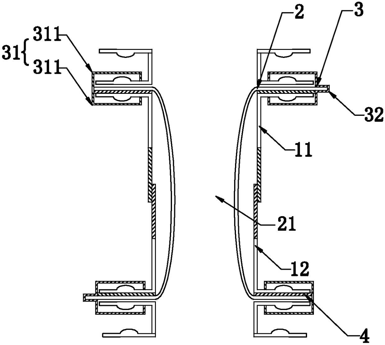
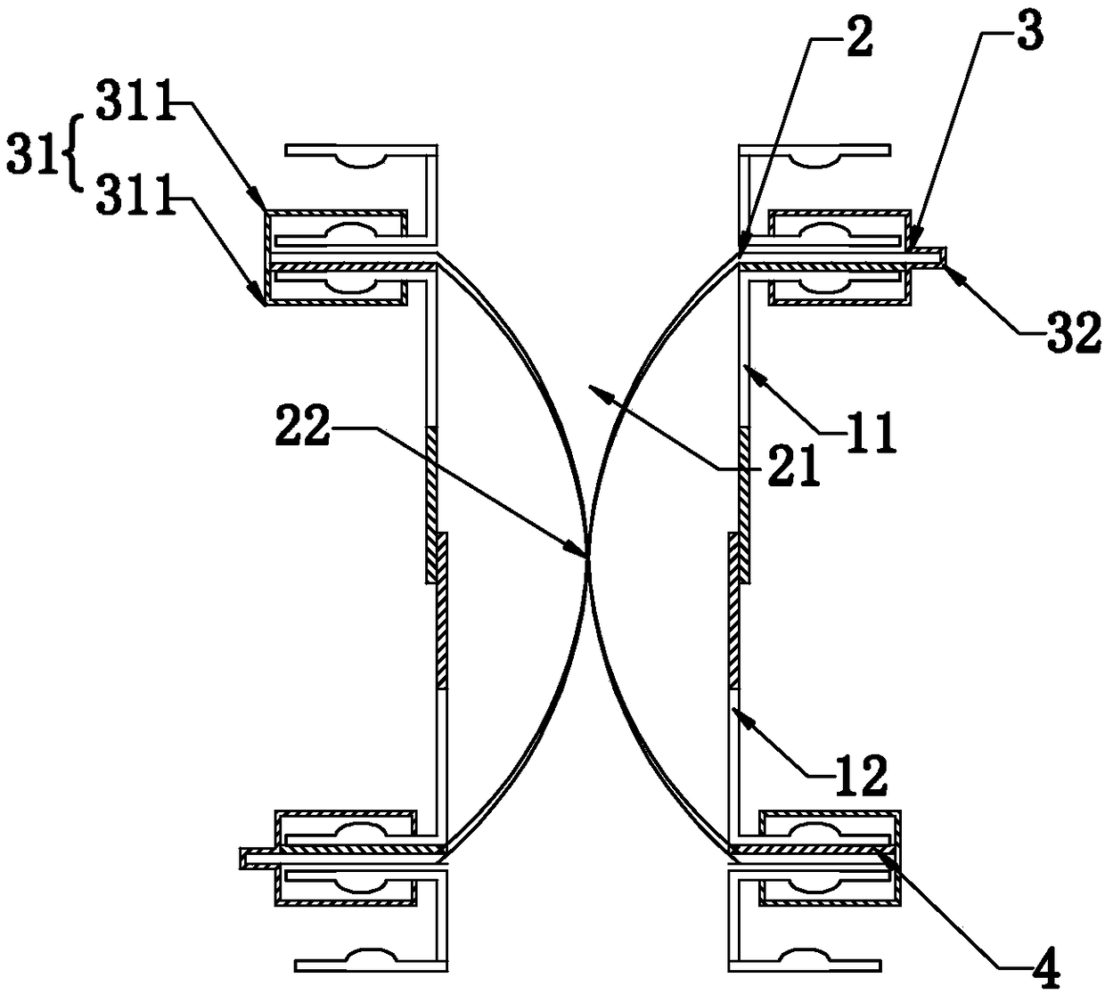
[0043] Such as Figure 1 ~ Figure 2 As shown, the present invention discloses a flexible valve. In a specific embodiment of the present invention, it includes an upper valve body 11, a lower valve body 12, and a membrane sleeve 2 with a material delivery channel 21. The two ends of the membrane sleeve 2 are respectively Connected with the upper valve body 11 and the lower valve body 12, the upper valve body 11 or / and the lower valve body 12 can be axially rotatably connected, and when the upper valve body 11 or / and the lower valve body 12 rotate axially, the membrane sleeve 2 is driven to rotate Twist and form a sealing point 22 .
[0044] In a specific embodiment of the present invention, the matching ends of the upper valve body 11 and the lower valve body 12 can be connected by threaded connection.
[0045] In a specific embodiment of the present invention, one end of the membrane sleeve 2 is installed at the feed inlet of the upper valve body 11 through the quick disassem...
Embodiment 2
[0051] Embodiment 2, the difference with embodiment 1 is
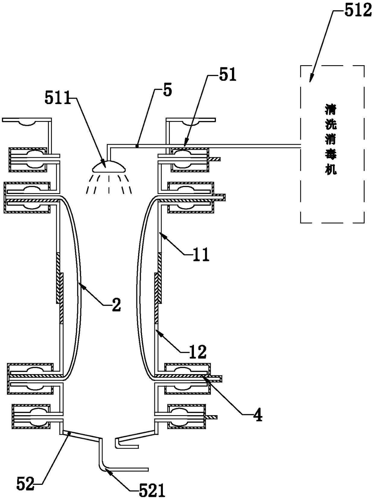
[0052] Such as image 3 As shown, in a specific embodiment of the present invention, an automatic cleaning and disinfection device 5 is also included, and the automatic cleaning and disinfection device 5 includes a combined online cleaning upper assembly 51 installed on the upper valve body 11 and an upper assembly installed on the lower valve body 12. The upper combined online cleaning lower assembly 52; the combined online cleaning upper assembly 51 includes a spraying part 511 for spraying the inner wall of the membrane casing 2 and a cleaning and disinfecting machine 512 for delivering cleaning liquid to the spraying part 511 The combined online cleaning lower assembly 52 includes a drain pipe 521 for discharging the cleaning liquid inside the lower valve body 12 .
[0053] In a specific embodiment of the present invention, the combined online cleaning upper assembly 51 and the combined online cleaning lower assem...
Embodiment 3
[0055] Embodiment 3, the difference with embodiment 1 is
[0056] Such as Figure 4 As shown, in a specific embodiment of the present invention, the outer wall of the upper valve body 11 and / or the outer wall of the lower valve body 12 is provided with an inflation interface 6, and the inflation interface 6 is provided with a sealing detection device 61, and the sealing The detection device 61 includes an air pressure monitoring device 612 connected to the inflation interface 6 through an external pressure control valve 611 .
[0057] By adopting the above-mentioned technical scheme: inert gas (for example: nitrogen) can be filled into the gap formed between the membrane sleeve, the upper valve body and the lower valve body through the inflation interface. The purpose of this setting is to protect the transported materials The function is to prevent the secondary pollution caused by the contact between the material and the air. Secondly, through the air pressure monitoring de...
PUM
 Abstract
Description
Claims
Application Information
 - R&D
- Intellectual Property
- Life Sciences
- Materials
- Tech Scout
- Unparalleled Data Quality
- Higher Quality Content
- 60% Fewer Hallucinations
Browse by: Latest US Patents, China's latest patents, Technical Efficacy Thesaurus, Application Domain, Technology Topic, Popular Technical Reports.
© 2025 PatSnap. All rights reserved.Legal|Privacy policy|Modern Slavery Act Transparency Statement|Sitemap|About US| Contact US: help@patsnap.com