Integrated surge immunity full-wave rectifier bridge structure

A full-wave rectification and anti-surge technology, which is applied in the direction of transforming equipment structural components, output power conversion devices, and converting AC power input to DC power output, etc. Insufficient compactness and other problems, to achieve the effect of saving PCB space, small size, and compact layout

Pending Publication Date: 2018-08-10
UNIV OF ELECTRONICS SCI & TECH OF CHINA +4
View PDF4 Cites 0 Cited by
  • Summary
  • Abstract
  • Description
  • Claims
  • Application Information

AI Technical Summary

Problems solved by technology

[0004] The Chinese Utility Model Patent No. 201621041504.9 discloses a full-wave rectifier bridge with bidirectional TVS input filtering, such as figure 2 Its circuit topology diagram is shown. The patent absorbs the surge current at the input end and clamps the input voltage within the withstand voltage range of the protected voltage by setting a bidirectional TVS diode at the input end of the rectifier bridge. However, the structure of the device is complex and the layout Not compact enough, high thickness, large volume, high cost, which is not conducive to the development of circuit miniaturization

Method used


Image

  • Integrated surge immunity full-wave rectifier bridge structure
  • Integrated surge immunity full-wave rectifier bridge structure
  • Integrated surge immunity full-wave rectifier bridge structure

Examples


Embodiment 1

[0037] Embodiment 1 An integrated anti-surge full-wave rectifier bridge structure

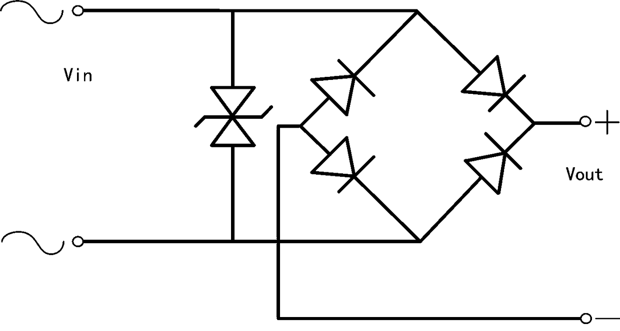
[0038] like image 3 As shown, the circuit schematic diagram of this embodiment is shown.

[0039] like Figure 4 As shown, this embodiment includes a plastic package 6, first to fourth diode chips 51 to 54, a unidirectional TVS chip 55, and first to fourth lead frames 11 to 14;

[0040] The top surfaces of the first diode chip 51 and the second diode chip 52 are both P-type, fixed on the second lead frame 12, and respectively connected to the first lead frame 11 and the third lead frame 13 by wires; The top surfaces of the diode chip 53 and the fourth diode chip 54 are both N-type, fixed on the fourth lead frame 14, respectively connected to the first lead frame 11 and the third lead frame 13 by wires; one-way TVS chip The top surface of 55 is P-type, fixed on the second lead frame 12, and connected to the fourth lead frame 14 by wires; the unidirectional TVS chip 55 and the first to fourth...

Embodiment 2

[0043] Embodiment 2 An integrated anti-surge full-wave rectifier bridge structure

[0044] like Figure 5 Shown is a schematic three-dimensional structure of this embodiment. The difference in structure between this embodiment and Embodiment 1 is that the first to fourth lead frames 11 to 14 and the carriers are all packaged in the cavity of the plastic sealing body 6 .

[0045] The other structures are the same as those of the first embodiment, and the working principle is the same as that of the embodiment.


PUM


Abstract

The present invention discloses an integrated surge immunity full-wave rectifier bridge structure. The structure comprises a plastic package body, four diode chips with the same technical indexes, anunidirectional TVS chip, and a first lead frame, a second lead frame, a third lead frame and a fourth lead frame; the unidirectional TVS chip has a P-type top surface, is fixed on the second lead frame, and is connected with the four lead frame through a wire; two of the four diode chips have P-type top surfaces, are fixed on the second lead frame and are respectively connected with the first leadframe and the third lead frame through wires; the other two of the four diode chips have N-type top surfaces, are fixed on the fourth lead frame, and are respectively connected with the first lead frame and the third lead frame through wires; and the first lead frame and the third lead frame are taken as input pins, and the second lead frame and the four lead frame are respectively taken as a positive pole pin and a negative pole pin. After the unidirectional TVS chip is arranged at a traditional rectifier bridge, the integrated surge immunity full-wave rectifier bridge structure is compact in layout, low in cost and thinner in thickness. The integrated surge immunity full-wave rectifier bridge structure is suitable for the technical field of electronic devices.

Description

technical field [0001] The invention belongs to the technical field of electronic devices and is used for protecting circuit elements at the output end of a rectifier bridge, in particular to an integrated anti-surge full-wave rectifier bridge structure. Background technique [0002] The transient surges caused by factors such as AC grid disturbance, lightning strikes, and start-stop of power equipment are important causes of damage to electronic equipment and lines. The rectifier bridge is used to convert the input alternating current into direct current and then output it. When the input alternating current has a surge and the surge exceeds the maximum withstand voltage of the load circuit and the circuit lacks protection components, the instantaneous energy will burn the device of the load circuit. like figure 1 (a) shows the normal AC input waveform of the power grid, figure 1 (b) shows the grid AC input waveform when there is a surge. [0003] Transient Voltage Suppr...

Claims


Application Information

Patent Timeline
Patent Type & Authority Applications(China)
IPC IPC(8): H01L25/07H01L23/495H01L23/31H02M7/00
CPCH01L23/49575H01L25/072H02M7/003H01L23/3107H01L2924/181H01L2224/48091H01L2224/48247H01L2224/73265H01L2924/00014H01L2924/00012
Inventor 洪吉忠范世杰范洋李蛇宏梁方彦赵建明刘继芝洪继霖
Owner UNIV OF ELECTRONICS SCI & TECH OF CHINA
Why Eureka
Try Eureka