Centrifugal compressor diffusor structure with blades being integrated with case and hub

A centrifugal compressor and diffuser technology, used in machines/engines, mechanical equipment, gas turbine devices, etc., can solve the difficulties in the design, modeling and processing of diffuser blades, serious distortion of diffuser blades, and problems in diffuser blades. Design difficulties and other problems, to achieve the effect of easy blade design and processing, without reducing the performance of the compressor, and reducing the mixing loss

Active Publication Date: 2018-08-10
INST OF ENGINEERING THERMOPHYSICS - CHINESE ACAD OF SCI
View PDF5 Cites 7 Cited by
  • Summary
  • Abstract
  • Description
  • Claims
  • Application Information

AI Technical Summary

Problems solved by technology

At the same time, in order to reduce the frontal area of ​​the engine and increase the thrust-to-weight ratio of the engine, it is necessary to reduce the radial size of the engine to the greatest extent. With the reduction of the outer diameter of the engine, the length of the radial diffuser of the centrifugal compressor decreases, and the diffuser The sharp increase of the diffuser load makes the flow channel separation in the vane channel very easy, resulting in an increase in the loss in the diffuser, making the design of the diffuser more difficult
[0003] In the prior art, by making the radial diffuser and the axial diffuser into an integrated structure (such as CN201410453415.4, CN200810196137.3, etc.), to reduce the gap between the radial diffuser and the axial diffuser The mixing loss in the turning section is conducive to reducing the maximum outer diameter of the diffuser under the premise of maintaining the same characteristics of the compressor, but the integrated diffuser blades will also change from the radial direction to the axial direction. Deflecting from the pressure surface to the suction surface, when the radial height of the diffuser is small, the diffuser blades will be twisted more seriously, resulting in greater difficulties in the design, shape and processing of the diffuser blades

Method used


Image

  • Centrifugal compressor diffusor structure with blades being integrated with case and hub
  • Centrifugal compressor diffusor structure with blades being integrated with case and hub
  • Centrifugal compressor diffusor structure with blades being integrated with case and hub

Examples


Embodiment Construction

[0025] The present invention will be further described in detail below in conjunction with embodiments. The following embodiments are for explaining the present invention, and the present invention is not limited to the following embodiments.

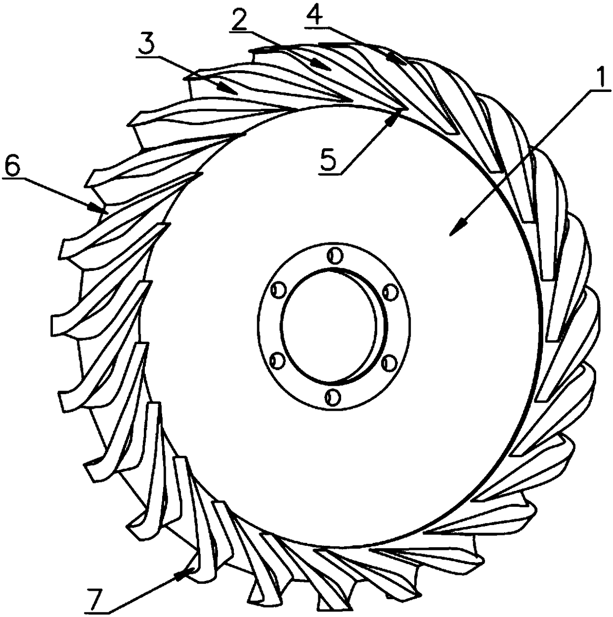
[0026] Such as Figure 1 to Figure 5 As shown, the diffuser structure of the centrifugal compressor with blades, casing and hub of the present invention includes a diffuser body 1. The diffuser body 1 is composed of a diffuser blade and a diffuser disc. The diffuser The number of blades is between 10 and 35. During processing, the diffuser blades can be processed by milling the diffuser airflow channel 9 on the diffuser disk. A plurality of diffuser blades are integrally formed and evenly distributed on the peripheral edge portion of the diffuser disc, the space between two adjacent diffuser blades is formed as a diffuser airflow channel 9, and each diffuser blade includes The radial blade segments on the end surface of the diffuser disk ...


PUM


Abstract

The invention discloses a centrifugal compressor diffusor structure with blades being integrated with a case and a hub. The centrifugal compressor diffusor structure with the blades being integrated with the case and the hub belongs to the technical field of middle-small aero-engine compressors, and is characterized in that a radial diffuser and an axial diffuser are connected into a whole, and aleading edge is designed into a sharp edge, so that the loss is reduced, and the outer diameter of each diffuser is reduced; and the blades are further integrated with the case of each diffuser and the hub, so that the distortion degrees of the blades of each diffuser are reduced, and the blades are convenient to design and process. The centrifugal compressor diffusor structure with the blades being integrated with the case and the hub provided by the invention can be directly applied to small aero-engines, the outer diameter of the engine can be reduced without increasing the processing costand reducing the compressor performance, and the thrust-weight ratio of the engine is improved.

Description

Technical field [0001] The invention belongs to the technical field of small and medium aeroengine compressors, and relates to a centrifugal compressor diffuser structure, in particular to a centrifugal compressor diffuser structure in which blades, casing and hub are fused, and can be installed at the inlet of the diffuser Under the condition of the same diameter, the maximum outer diameter of the diffuser is reduced, and the distortion of the pressure surface and suction surface of the diffuser blade is also reduced. It is especially suitable for small and medium-sized aero-engine high-pressure centrifugal compressors. Background technique [0002] Centrifugal compressors have been widely used in small gas turbines and small and medium aeroengines due to their advantages of high single-stage pressure ratio, wide working range, simple structure and high reliability. As the pressure ratio of the centrifugal compressor increases, the unevenness of the airflow at the outlet of the ...

Claims


Application Information

Patent Timeline
IPC IPC(8): F04D29/46F02C3/08
CPCF02C3/085F04D29/444F04D29/464
Inventor 韩戈龚建波郭磊胡春艳穆勇卢新根徐纲
Owner INST OF ENGINEERING THERMOPHYSICS - CHINESE ACAD OF SCI
Why Eureka
Try Eureka