A controllable expansion extrusion soil device for geotechnical engineering

A technology of geotechnical engineering and soil mass, which is applied in basic structure engineering, construction, etc., can solve the problems of side leakage of slurry, waste, waste of raw materials, etc., and achieve the effect of accumulation and fixation

Inactive Publication Date: 2020-09-22
叶文龙 +7
View PDF1 Cites 0 Cited by
  • Summary
  • Abstract
  • Description
  • Claims
  • Application Information

AI Technical Summary

Problems solved by technology

[0005] The object of the present invention is to provide a controllable expansion and extrusion soil device for geotechnical engineering, to solve the problem that the existing geotechnical engineering expansion and extrusion soil device proposed in the above background technology is not convenient for grouting. The disassembly work between the grout pipe body and the expansion extrusion cylinder, after the grouting is completed, the grouting pipe is directly connected to the expansion extrusion cylinder and put into use, which wastes raw materials. The change of the size and shape of the expansion extrusion cylinder automatically adjusts the elongation, and the expansion extrusion cylinder is not convenient to automatically realize the sealing of the expansion extrusion cylinder after the grouting is completed, which may easily lead to side leakage of grout and waste. When the expansion extrusion cylinder is stacked and used, due to the smooth surface of the extrusion cylinder, it is prone to collapse

Method used


Image

  • A controllable expansion extrusion soil device for geotechnical engineering
  • A controllable expansion extrusion soil device for geotechnical engineering
  • A controllable expansion extrusion soil device for geotechnical engineering

Examples


Embodiment Construction

[0025] The following will clearly and completely describe the technical solutions in the embodiments of the present invention with reference to the accompanying drawings in the embodiments of the present invention. Obviously, the described embodiments are only some, not all, embodiments of the present invention. Based on the embodiments of the present invention, all other embodiments obtained by persons of ordinary skill in the art without creative efforts fall within the protection scope of the present invention.

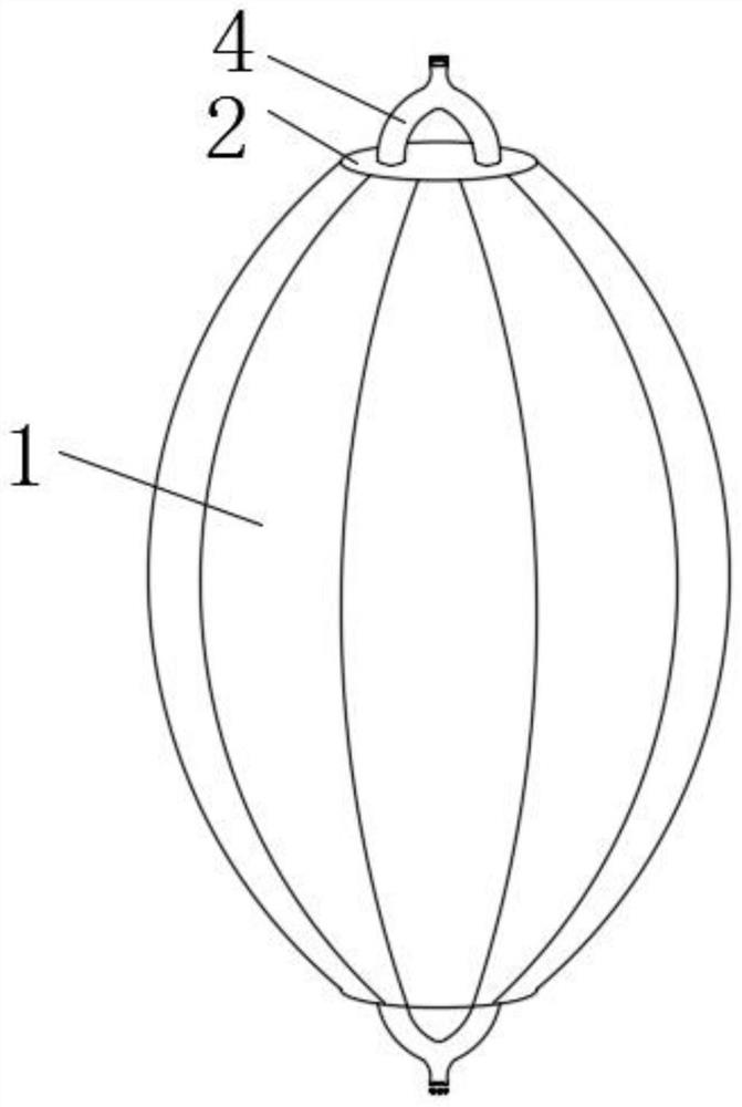
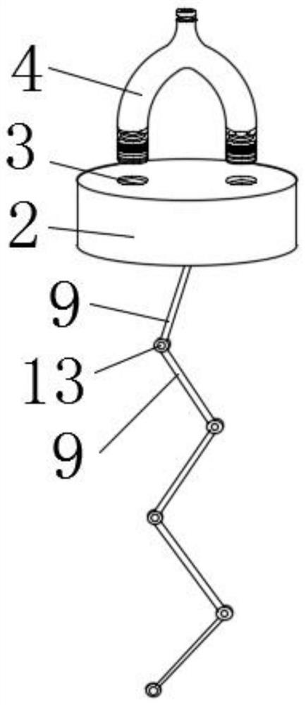
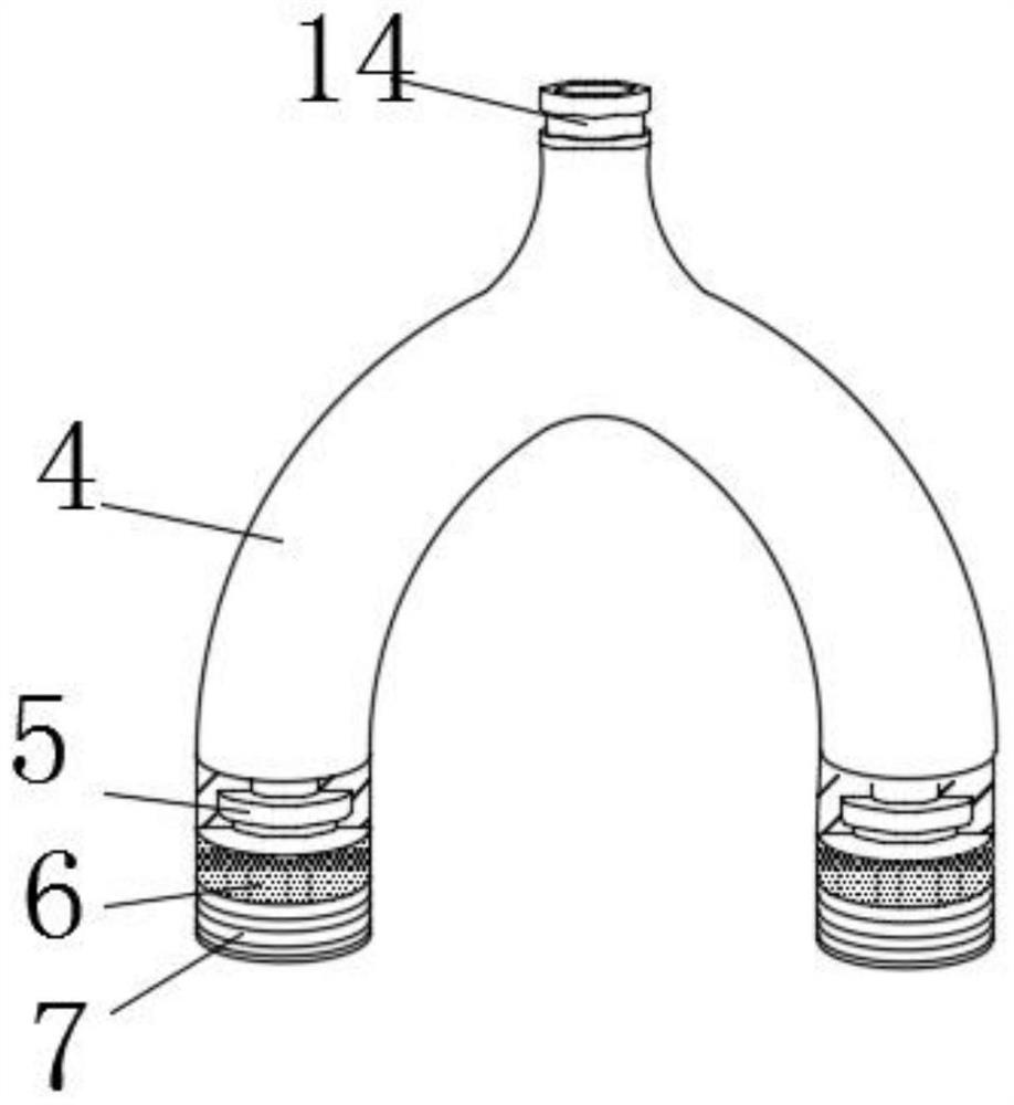
[0026] see Figure 1-5 , the present invention provides a technical solution: a controllable expansion extrusion soil device for geotechnical engineering, comprising an expansion extrusion cylinder 1, the upper and lower ends of the expansion extrusion cylinder 1 are sealed and packaged with an injection body 2, the injection body The upper surface of the 2 is provided with a threaded hole 3 and a U-shaped grouting pipe 4, and the lower end of the U-shaped grouting...


PUM


Abstract

The invention discloses a controllable expansive soil extrusion device for geotechnical engineering, and belongs to the technical field of civil engineering. The controllable expansive soil extrusiondevice comprises an expansive extrusion cylinder, wherein the upper end and the lower end of the expansive extrusion cylinder are both sealed and packaged with injection bodies, the upper surface of each injection body is provided with a threaded hole and a U-shaped grouting pipe, an adjusting handle is movably clamped to the lower end of each U-shaped grouting pipe through a chuck, and a threadedpipe rod is arranged at the bottom of the adjusting handle. The bottom of the adjusting handle is in threaded connection with the inner wall of each threaded hole through the threaded pipe rod, and arotating platform body and a steel bar fixing piece are arranged in the center of the bottom of each injection body. The top end of the steel bar fixing piece is movably connected with the center ofthe bottom of each injection body through the rotating platform body, and injection slot holes are formed in the lower surfaces of the injection bodies at the two sides of the rotating platform body.The controllable expansive soil extrusion device for the geotechnical engineering is simple in structure and convenient to use, and can be conveniently applied to geotechnical construction through therationalization grouting treatment of the expansive extrusion cylinder and a convenient stacking mode.

Description

technical field [0001] The invention relates to the technical field of civil engineering, in particular to a controllable expansion extrusion soil device for geotechnical engineering. Background technique [0002] When building a house, due to the influence of construction or geographical reasons, the building will tilt. If the building tilts too seriously, it will easily lead to the collapse of the building and affect the lives of the surrounding residents. Here, it is necessary to The building is rectified by certain means, and the bottom of the building is grouted by punching holes at the bottom of the building, and the jacking of the building is realized through the extrusion force generated when the grout solidifies, and at the same time During grouting, concrete with relatively strong stability is usually used for expansion and extrusion, which can effectively prevent the occurrence of tilting phenomenon again after correction. [0003] When the existing geotechnical ...

Claims


Application Information

Patent Timeline
Patent Type & Authority Patents(China)
IPC IPC(8): E02D35/00
CPCE02D35/00
Inventor 叶文龙信长昊魏永青鄂飞金淳哲熊帝李广臣王超
Owner 叶文龙
Why Eureka
Try Eureka