Directional and dual-frequency omnidirectional combined vehicle antenna

A directional antenna, omnidirectional antenna technology, applied to antennas, antennas suitable for movable objects, antenna arrays and other directions, can solve problems such as performance impact, and achieve the effect of small overall size, low profile and low cost

Pending Publication Date: 2018-08-07
TONGYU COMM INC
View PDF0 Cites 5 Cited by
  • Summary
  • Abstract
  • Description
  • Claims
  • Application Information

AI Technical Summary

Problems solved by technology

However, when the UHF omni-directional antenna is close to a large metal roof, the performance is significantly affected by the roof because the distance between the two and the size of the roof are electrically small and electrically large, and the impedance mismatch is particularly serious

Method used


Image

  • Directional and dual-frequency omnidirectional combined vehicle antenna
  • Directional and dual-frequency omnidirectional combined vehicle antenna
  • Directional and dual-frequency omnidirectional combined vehicle antenna

Examples


Embodiment Construction

[0053] The preferred embodiments of the invention are given below in conjunction with the accompanying drawings to describe the technical solutions of the present invention in detail. Here, the present invention will be described in detail with reference to the accompanying drawings. It should be noted that the preferred implementation examples described here are only used to illustrate and explain the present invention, and are not used to limit or limit the present invention.

[0054] The present invention aims to provide a directional / omnidirectional, high-gain, high-efficiency, miniaturized, low-profile, simple-structured, low-cost, and mass-produced combined vehicle antenna for high-speed rail wireless communication, and is a high-gain dual It provides a useful reference method for the design and improvement of frequency omnidirectional antenna and bidirectional directional antenna.

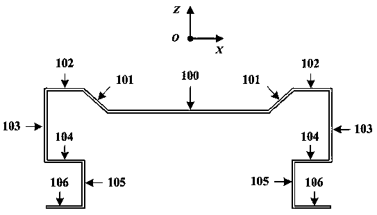
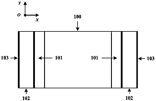
[0055] Such as Figure 13 As shown, the directional and dual-frequency omnidirectional...


PUM


Abstract

The invention relates to a directional and dual-frequency omnidirectional combined vehicle antenna. The directional and dual-frequency omnidirectional combined vehicle antenna comprises a dual-frequency omnidirectional antenna assembly, a directional antenna assembly, an antenna feed assembly and the horizontal common floor. The antenna floor is designed into two separate split structures, the twoseparate split structures are connected through capacitive coupling, the lower floor is connected with a vehicle top metal plate, a technical problem of metal vehicle top interference on a low frequency omnidirectional antenna is solved, moreover, UHF and GSM bands are realized through a dual-frequency omnidirectional antenna, and antenna miniaturization and the compact structure are realized. Ashielding problem of the directional antennas on the omnidirectional antenna is further solved, through cleverly arranging the two directional antennas and one UHF / GSM dual-frequency omnidirectional antenna, the omnidirectional antenna is arranged at the middle of the upper floor, the position is relatively high, the directional antennas are arranged at left and right ends of the lower floor, theposition is relatively low, and thereby interference of the later on the previous is reduced.

Description

technical field [0001] The invention relates to a radio communication antenna device and technology, in particular to a directional and dual-frequency omnidirectional combined vehicle antenna and its technology. Background technique [0002] With its fast, comfortable, safe, economical and other advantages, high-speed railway has become the preferred way for the general public to travel. After more than ten years of development, China's high-speed rail ranks first in the world in terms of comprehensive technology, operating mileage and cost advantages, and has become a beautiful business card of China's technological innovation. At present, the operating mileage of China's high-speed rail has exceeded 25,000 kilometers, which is more than the sum of the mileage of other countries in the world, and it continues to grow every year. In addition, China's high-speed rail has gone abroad and won one after another foreign high-speed rail construction orders. It is believed that i...

Claims


Application Information

Patent Timeline
IPC IPC(8): H01Q1/32H01Q1/48H01Q1/50H01Q5/10H01Q5/20H01Q21/00H01Q21/29
CPCH01Q1/3216H01Q1/48H01Q1/50H01Q5/10H01Q5/20H01Q21/00H01Q21/0006H01Q21/293
Inventor 李道铁谭想吴中林刘木林
Owner TONGYU COMM INC
Why Eureka
Try Eureka