Vacuum processing device

The technology of a vacuum processing device and a vacuum tank is applied in the directions of vacuum evaporation coating, transportation and packaging, ion implantation coating, etc. , the effect of reducing the length

Active Publication Date: 2018-08-03
ULVAC INC
View PDF16 Cites 5 Cited by
  • Summary
  • Abstract
  • Description
  • Claims
  • Application Information

AI Technical Summary

Problems solved by technology

[0006] In addition, in such prior art, since substrates in multiple rows and multiple columns are placed on a tray, all the processing area and accompanying equipment need to be large enough to completely cover the surface area of ​​the tray. As a result, including the above-mentioned The problem becomes a big obstacle in narrowing the installation space
[0007] However, if there are trays on which the substrates to be processed are placed in a single row, even if a plurality of the trays are placed in the conveying direction, after starting the processing of the substrates placed in front of the trays and completing the loading During the processing of the substrate placed at the rear end of the tray, it is necessary to set the processing remaining area covering both: the length from the second sheet to the rear end substrate when the substrate at the front end of the tray starts processing; During processing, the length from the substrate at the front of the tray to the substrate at the rear end; this has the problem of not being able to sufficiently save space

Method used


Image

  • Vacuum processing device
  • Vacuum processing device
  • Vacuum processing device

Examples


Embodiment Construction

[0062] Embodiments of the present invention will be described in detail below with reference to the drawings.

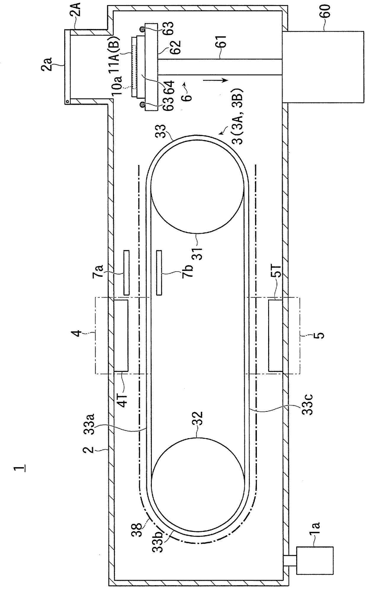
[0063] figure 1 It is a schematic configuration diagram showing the whole of an embodiment of the vacuum processing apparatus according to the present invention.

[0064] Such as figure 1 As shown, the vacuum processing apparatus 1 of this embodiment has the vacuum tank 2 which is connected to the vacuum exhaust device 1a and forms a single vacuum atmosphere.

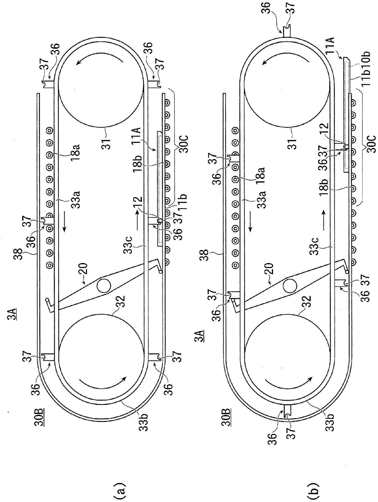
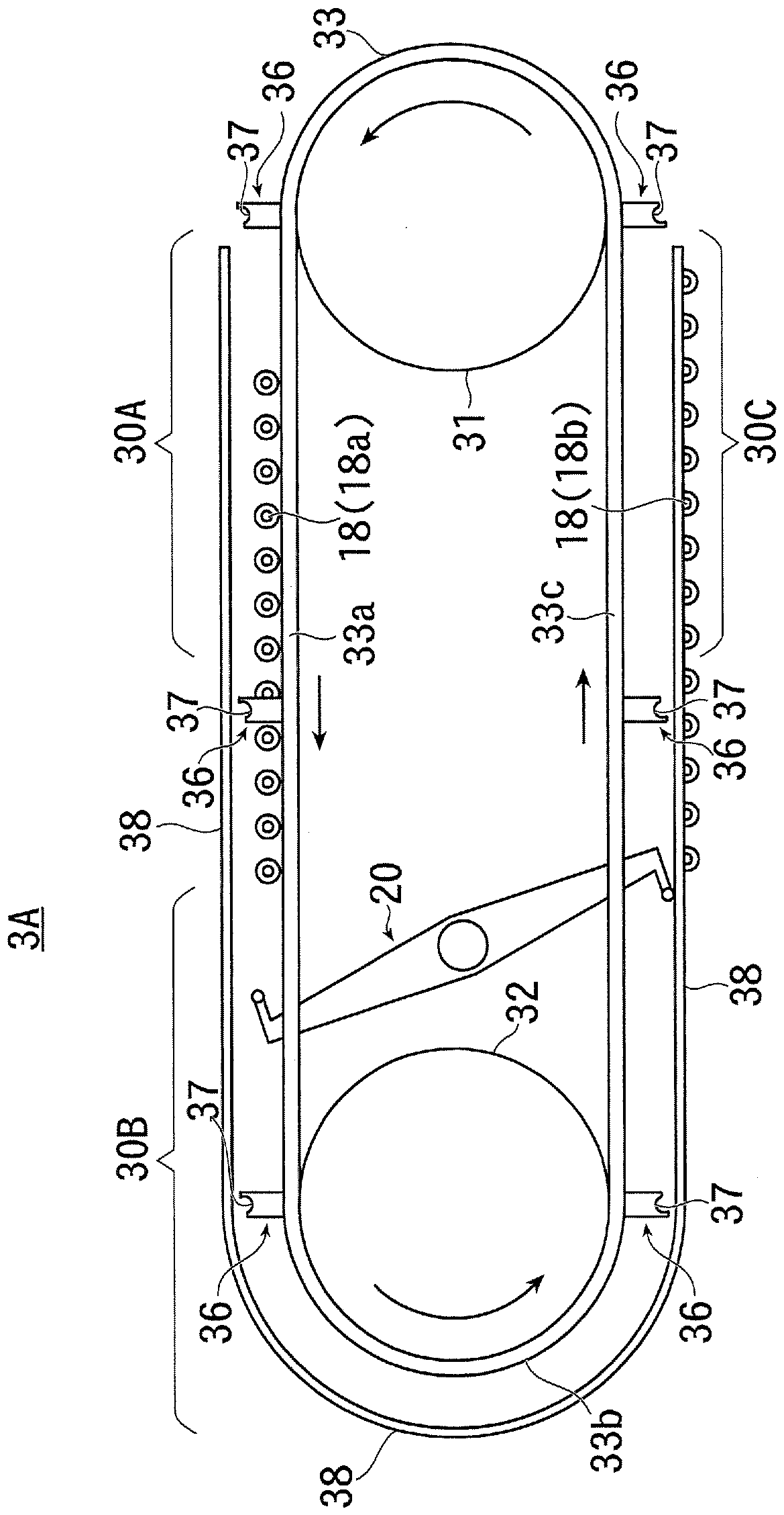
[0065] Inside the vacuum chamber 2 is provided a substrate holder transport mechanism 3 for transporting a substrate holder 11 to be described later along a transport path.

[0066] The substrate holder transport mechanism 3 is configured to continuously transport a plurality of substrate holders 11 holding the substrate 10 via, for example, trays.

[0067] Here, the detailed structure of the substrate holder conveying mechanism 3 will be described later. The substrate holder conveying mechanism 3 has, for ...


PUM


Abstract

The present invention provides a pass-through vacuum processing device in which adequate space savings can be achieved. This vacuum processing device 1 has: a vacuum chamber 2 in which a single vacuumatmosphere is formed; first and second processing regions 4, 5 provided within the vacuum chamber 2, the first and second processing regions 4, 5 having processing sources for performing processes ona flat processing surface of a substrate 10; and a conveyance drive member 33 constituting part of a conveying path for conveying the substrate 10 so as to pass through the first and second processing regions 4, 5. The conveying path is formed so as to comprise a series of annular shapes when projected on a plane (a vertical plane) that includes a normal at an arbitrary point on the processing surface of the substrate 10 being conveyed and a trajectory line segment described by the arbitrary point on the processing surface of the substrate 10 when the substrate 10 passes rectilinearly throughthe first and second processing regions 4, 5.

Description

technical field [0001] The present invention relates to the technology of a vacuum processing apparatus that performs vacuum processing such as film formation on a substrate in vacuum, and particularly relates to the technology of a through-type vacuum processing apparatus that performs processing while moving a substrate holder that holds a plurality of substrates. Background technique [0002] Conventionally, there is known a vacuum processing apparatus that performs processes such as film formation while placing and passing a plurality of substrates to be processed on a substrate holder such as a tray. [0003] As such a vacuum processing apparatus, an apparatus having a circular conveyance path is also known. In addition, in the prior art, it is shown that a substrate to be processed is introduced into the conveyance path in the process of transferring the substrate to be processed. (loading) and eject (unloading) processed substrates from the transport path. [0004] I...

Claims


Application Information

Patent Timeline
Patent Type & Authority Applications(China)
IPC IPC(8): C23C14/56B65G17/00B65G17/32B65G49/06C23C14/34H01L21/677
CPCC23C14/34C23C14/50C23C14/568H01L21/67109H01L21/67207H01L21/67706H01L21/67715H01L21/6776B65G17/12B65G17/32B65G49/061B65G2201/022H01L21/677B65G17/326
Inventor 中尾裕利
Owner ULVAC INC
Why Eureka
Try Eureka