
Laser path and laser welding method of a laser welding point

A technology of laser welding and welding points, applied in laser welding equipment, welding equipment, metal processing equipment, etc., can solve problems such as poor penetration rate, low yield rate, and small pulling force

Active Publication Date: 2020-01-24
WUHAN LINGYUN PHOTOELECTRONICS SYST
View PDF7 Cites 0 Cited by
  • Summary
  • Abstract
  • Description
  • Claims
  • Application Information

AI Technical Summary

Problems solved by technology

The elastic thin-walled corrugated sheet in the sensor or temperature controller is widely used in welding with a thickness of 0.05-0.1mm. However, in the existing welding equipment, lamp pumps, QCW, and CO2 gas lasers are basically used. At present In the process used, there are certain problems for spot welding between thin sheet materials below 0.2 mm. Since these types of lasers use each single pulse energy to reach the focal level, the focal spot is larger than 0.2 mm. For thin materials For example, it is easy to produce pores, the thermal conductivity is too large, the penetration rate is poor, the joint is easy to catalyze and soften, the single-point energy pulse is large, it is easy to cause gas overflow during welding, and it is easy to form cracks after welding. Through welding, the quality of welding on thin sheets is not high, and the yield rate is not high

Method used

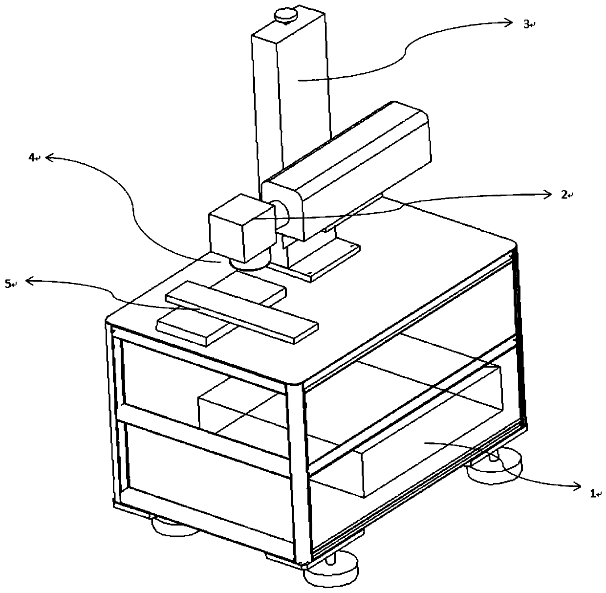
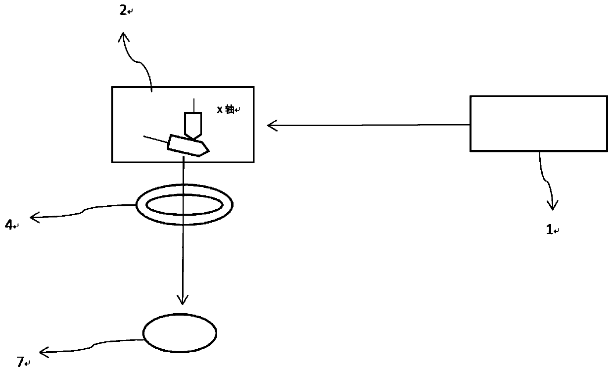
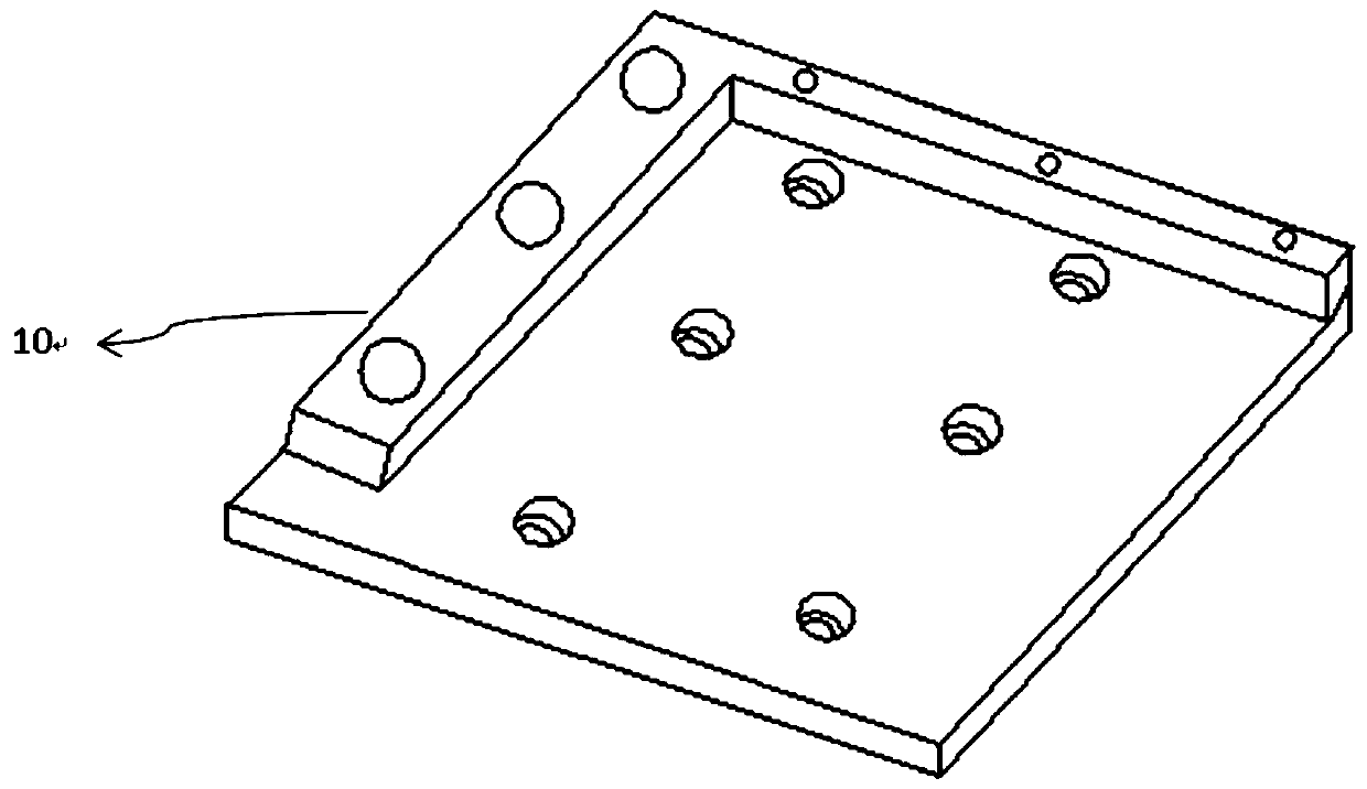

Image

  • Laser path and laser welding method of a laser welding point
  • Laser path and laser welding method of a laser welding point
  • Laser path and laser welding method of a laser welding point

Examples


Embodiment Construction

[0039] The light energy of the nanosecond short-pulse laser in this embodiment, the laser parameters are wavelength 1060-1070 nanoseconds, average power between 50-200 watts, beam quality M2 factor is less than or equal to 1.5, and its pulse setting width is 1-800 nanoseconds , the minimum pulse width is 1 nanosecond, the repetition frequency range is 1-2000 kHz, the maximum single pulse energy is less than or equal to 5 mJ, and the laser output spot size is 6-9 mm. The ellipticity of the output spot beam is greater than 95%, and the divergence angle of the beam is less than 0.5 milliradians.

[0040] The shape of the laser focus spot is a circle, and the focal length of the field lens is 100-240 mm. The optional lens has a laser spot size of 0.02-0.07 mm after being focused by the field lens. The purpose of this step is to select a reliable depth of focus for welding. The focus spot size is proportional to the focal length, the shorter the focal length, the smaller the spot....


PUM

PropertyMeasurementUnit
thicknessaaaaaaaaaa

Abstract

The invention discloses a laser path of a laser welding point, and a laser welding method. The laser welding method comprises the steps of fixing a product to be welded onto a two-dimensional platformthrough a fixture, utilizing a pulse laser for scanning welding a welding point in a welding area of the product to be welded, and dividing a laser scanned path graph of the welding point into threesegments, wherein the first segment is a straight-line segment or a curved segment, the second segment is formed by multiple reciprocating disjoint straight-line segments or curved segments, startingpoints of each two adjacent straight-line segments or curved segments are connected through a transition segment, the third segment is a straight-line segment or a curved segment, and the first segment, the second segment and the third segment are sequentially connected; and crossing the straight-line segments or the curved segments of the first segment and the second segment, crossing the straight-line segments or the curved segments of the third segment and the second segment, and during a laser scanning welding process, blowing a protection gas to the welding point. According to a speciallyedited point-shaped welding graph, a thin slice is welded through a single-pulse superposition track manner, multiple small molten pools are formed in the thin slice material, and the welding point with a large tensile force is obtained.

Description

technical field [0001] The invention belongs to the laser welding technology, in particular to a laser welding technology for electronic product components, in particular to the laser scanning path during the laser welding process. Background technique [0002] Laser welding is widely used in the electronics industry, especially in the microelectronics industry. Due to the small heat-affected zone of laser welding, rapid heating and low thermal stress, it is showing unique advantages in the packaging of integrated circuits and semiconductor device housings. In the development of vacuum devices, laser welding has also been applied, such as molybdenum Focusing electrode and stainless steel support ring, fast hot cathode filament assembly, etc. The elastic thin-walled corrugated sheet in the sensor or temperature controller is widely used in welding with a thickness of 0.05-0.1mm. However, in the existing welding equipment, lamp pumps, QCW, and CO2 gas lasers are basically use...

Claims


Application Information

Patent Timeline
Patent Type & Authority Patents(China)
IPC IPC(8): B23K26/21
CPCB23K26/21
Inventor 周常多
Owner WUHAN LINGYUN PHOTOELECTRONICS SYST
Learn More