Parallel Ditch Clamp Lap

A technology of lap joints and wire clamps, which is applied in the direction of multi-core cable end parts, etc., and can solve problems such as low work efficiency and inconvenient operation

Active Publication Date: 2019-05-21
STATE GRID ZHEJIANG XINCHANG POWER SUPPLY +3
View PDF6 Cites 0 Cited by
  • Summary
  • Abstract
  • Description
  • Claims
  • Application Information

AI Technical Summary

Problems solved by technology

[0003] At present, multiple people are required to cooperate with multiple tools to operate the lapping of parallel trench clamps, which are used to fix the parallel trench clamps, lock the lead wires, and fix the pressure cylinder respectively. The operation is inconvenient and the work efficiency is low.

Method used


Image

  • Parallel Ditch Clamp Lap
  • Parallel Ditch Clamp Lap
  • Parallel Ditch Clamp Lap

Examples


Embodiment Construction

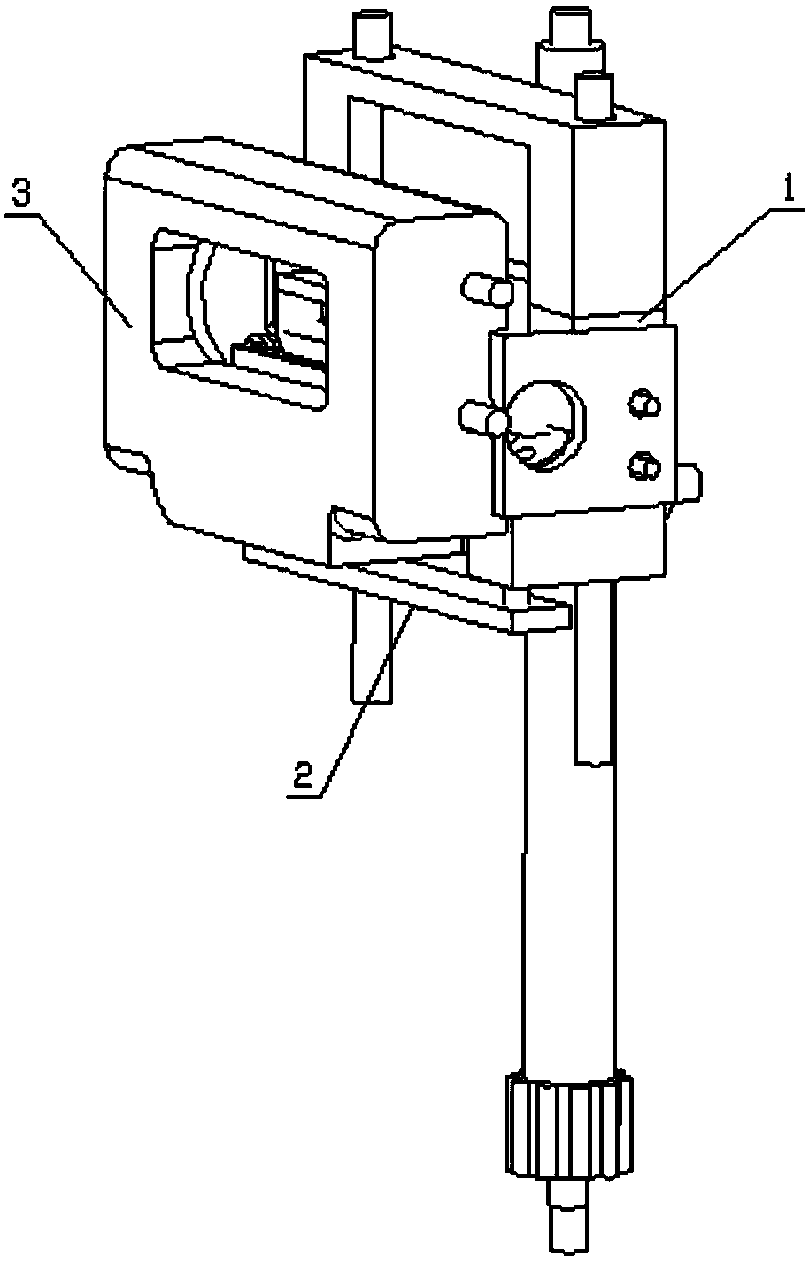
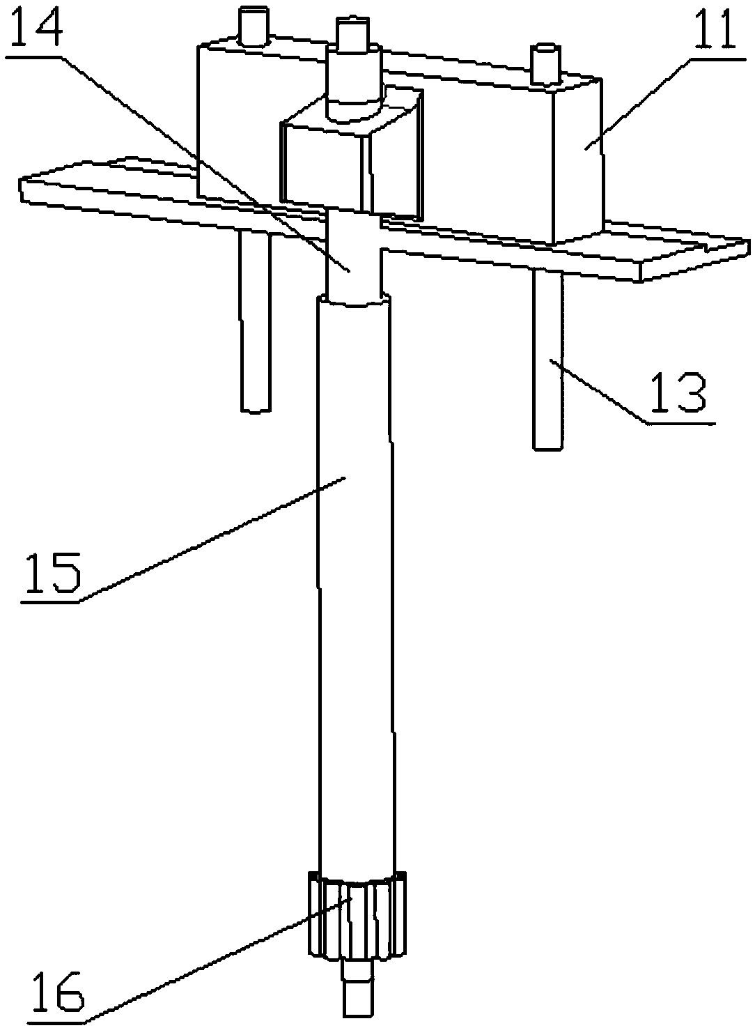
[0021] Such as Figure 1 to Figure 3 As shown, the parallel ditch wire clamp overlapper includes a wire clamp fixer 1, a lead wire locker 2 and a press cylinder fixer 3, and the wire clamp fixer 1 includes a first wire clamp fixing block 11, which is located on the first The second wire clamp fixed block 12 on the lower side of the wire clamp fixed block, the guide connecting rod 13 connecting the first wire clamp fixed block 11 and the second wire clamp fixed block 12, makes the first wire clamp fixed block 11 and the second wire clamp fixed block 12 The wire clip holder control structure for clamping or loosening the parallel trench wire clip, the second wire clip fixing block 12 is provided with a lead wire passing groove 121 for the lead wire to pass through transversely.

[0022] refer to figure 2 and image 3 As shown, the first wire clamp fixing block 11 is provided with a first U-shaped groove 111, the second wire clamp fixing block 12 is provided with a second U-sh...


PUM


Abstract

The invention discloses a parallel groove clamp lap-joint device, which comprises a clamp fixing device, a lead locking device and a pressure cylinder fixing device, wherein the clamp fixing device comprises a first clamp fixing block, a second clamp fixing block arranged at the lower side of the first clamp fixing block, a guide connecting rod connecting the first clamp fixing block and the second clamp fixing block and a clamp fixing device control structure which enables the first clamp fixing block and the second clamp fixing block to clamp or loosen a parallel groove clamp, the second clamp fixing block is provided with a lead pass-through slot provided for a lead to transversely pass through, the lead locking device comprises a locking block arranged in the lead pass-through slot anda lead locking device control structure which controls the locking block to move so as to lock or loosen the lead, and the pressure cylinder fixing device comprises a pressure cylinder fixing block connected with the second clamp fixing block and pressure cylinder clamping pieces arranged at the left and right sides of the pressure cylinder fixing block respectively. The parallel groove clamp lap-joint device can be operated by one person, and can complete lap joint through one set of tools, thereby greatly improving the lap-joint efficiency of the parallel groove clamp.

Description

technical field [0001] The invention relates to electric power engineering technology, in particular to the lap joint technology of parallel ditch line clips. Background technique [0002] The parallel trench clamp is used for the connection of small and medium-sized aluminum stranded wires or steel-cored aluminum stranded wires and the steel stranded wires of overhead lightning conductors at positions that do not bear tension, and is also used for jumper connections of non-linear pole towers. [0003] At present, multiple people are required to cooperate with multiple tools to operate the overlapping of the parallel groove clamps, which are respectively used to fix the parallel groove clamps, lock the lead wires, and fix the pressure cylinder, which is inconvenient to operate and low in work efficiency. Contents of the invention [0004] The technical problem to be solved by the present invention is to provide a parallel ditch wire clip lap jointer which can be operated c...

Claims


Application Information

Patent Timeline
Patent Type & Authority Patents(China)
IPC IPC(8): H01R11/11
CPCH01R11/11
Inventor 何九葛梁本炎吴冬钢陈琪明张锋朱诚聂建波竺德林
Owner STATE GRID ZHEJIANG XINCHANG POWER SUPPLY
Why Eureka
Try Eureka