Eureka AIR delivers breakthrough ideas for toughest innovation challenges, trusted by R&D personnel around the world.

A kind of automatic threading method and threading device for traveler of ring spinning frame

A threading method and traveler technology, which are used in spinning machines, piecing devices, textiles and papermaking, etc., can solve the problem of inability to rotate the traveler, and achieve the effect of shortening threading time, improving success rate and speeding up efficiency.

Active Publication Date: 2022-08-09
PINTER YUHUA CHINA TECH CO LTD
View PDF10 Cites 0 Cited by
  • Summary
  • Abstract
  • Description
  • Claims
  • Application Information

AI Technical Summary

Problems solved by technology

[0004] Then the above-mentioned patents and prior art cannot rotate the traveler stopped at any position of the steel ring, but for automatic disconnection lap, turning the traveler stopped at any position of the steel ring is to realize the automatic threading of the traveler prerequisite

Method used


Image

  • A kind of automatic threading method and threading device for traveler of ring spinning frame
  • A kind of automatic threading method and threading device for traveler of ring spinning frame
  • A kind of automatic threading method and threading device for traveler of ring spinning frame

Examples


specific Embodiment 1

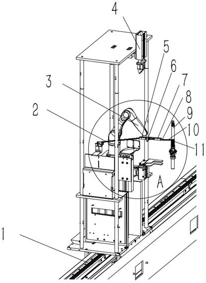
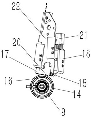
[0048] A ring spinning machine traveler automatic threading device, comprising a wire feeder 6 and a circulation generator 7, the wire feeder 6 comprises a fixing plate 22 fixed on the end 5 of the mechanical arm on the mechanical arm 3, and the mechanical arm 3 is fixed on the platform 2, the platform 2 moves along the guide rail 1, the left side of the fixing plate 22 is provided with a first venturi, a yarn fixing device and a second venturi, and the yarn fixing device is located at the first venturi and the second venturi. In the middle of the inner tube, the end of the second venturi tube is provided with a yarn nozzle 17, and the other side of the fixing plate is provided with a yarn fixing shaft 15. Both the yarn nozzle 17 and the yarn fixing shaft 15 are yarn clamping devices 8 , the two cooperate to form the threading part 20 of the yarn.

[0049] In use, the first venturi tube sucks the yarn 10, after passing through the yarn fixing device, it enters the second ventu...

specific Embodiment 2

[0051] An automatic threading method for a traveler of a ring spinning frame,

[0052] As soon as a yarn break is detected at one of the spinning stations of the ring spinning frame, the robot arm 3 receives a signal from the processing and control of the system, moves along the guide 1 and is centered in front of the spindle tube for the yarn break spinning station.

[0053] The first venturi tube sucks the yarn 10, after passing through the yarn fixing device, it enters the second venturi tube, and is ejected from the yarn nozzle, and the yarn end 11 contacts the yarn tube 9 and is wound around the yarn tube;

[0054] - Step a) Through the action of the robotic arm, under the combined action of the two types of yarn gripping devices in the yarn gripping device 8, namely the yarn fixing shaft 15 and the yarn nozzle 17, the yarn fixing shaft 15 and the yarn nozzle 17 work together. A threading portion 20 of the yarn is formed between the nozzles 17 .

[0055] - Step b) The r...


PUM


Abstract

The invention discloses an automatic threading device for a traveler of a ring spinning frame, comprising a thread feeder for arranging the yarn into a linear tension state, the thread feeder comprising at least two yarn clamps separated from each other The two clamping devices are fixed on the same fixing base, the fixing base is provided with a connecting part fixed on the mechanical arm, and the two yarn clamping devices respectively clamp the two ends of the yarn to form the threading part of the yarn , a circulation generator for forming a surrounding airflow at the ring; the beneficial effect of the present invention is: the surrounding airflow makes the traveler can be blown at any position of the ring, and rotates around the ring, through the threading part and the steel ring. The axis of the collar forms an included angle a to ensure that the threading part of the traveler hangs in the traveler.

Description

technical field [0001] The invention belongs to the technical category of threading after yarn breakage in the technical field of spinning of ring spinning frames, and in particular relates to an automatic threading method and threading device for ring traveler threading of ring spinning frames . Background technique [0002] The friction pair of ring and traveler is the key equipment for twisting and winding on the ring spinning frame. The spindle rotates with the bobbin at high speed, and the yarn on the bobbin drives the traveler to slide along the edge of the ring. Therefore, the traveler is a passive movement on the steel ring, which plays the role of guiding traction. [0003] Among them, the invention patent CN201880072134.0 provides a balloon control ring of a ring spinning frame, which can be opened or unfolded to allow operators to repair yarn breaks during spinning operations, and will not hinder the doffer's air The loop control ring also provides an improved o...

Claims


Application Information

Patent Timeline
Patent Type & Authority Patents(China)
IPC IPC(8): D01H7/60D01H15/00
CPCD01H7/606D01H15/00
Inventor 刘文田
Owner PINTER YUHUA CHINA TECH CO LTD
Why Eureka
Eureka Blog
Learn More