Method and device for automatically detecting bad point coordinates, device and storage medium

An automatic detection device and automatic detection technology, applied in nonlinear optics, instruments, optics, etc., to achieve the effect of reducing steps and manual operations

Active Publication Date: 2018-07-27
BOE TECH GRP CO LTD +1
View PDF7 Cites 2 Cited by
  • Summary
  • Abstract
  • Description
  • Claims
  • Application Information

AI Technical Summary

Problems solved by technology

Since one Shorting Bar test cannot accurately report bad coordinates, only the range of difference coordinates can be reported, and the reporting of bad coordinates requires personnel to perform two full contact and three full contact tests before panel repair can be performed to improve good products

Method used


Image

  • Method and device for automatically detecting bad point coordinates, device and storage medium
  • Method and device for automatically detecting bad point coordinates, device and storage medium
  • Method and device for automatically detecting bad point coordinates, device and storage medium

Examples


Embodiment Construction

[0030] The application will be further described in detail below in conjunction with the accompanying drawings and embodiments. It should be understood that the specific embodiments described here are only used to explain related inventions, rather than to limit the invention. It should also be noted that, for ease of description, only parts related to the invention are shown in the drawings.

[0031] It should be noted that, in the case of no conflict, the embodiments in the present application and the features in the embodiments can be combined with each other. The present application will be described in detail below with reference to the accompanying drawings and embodiments.

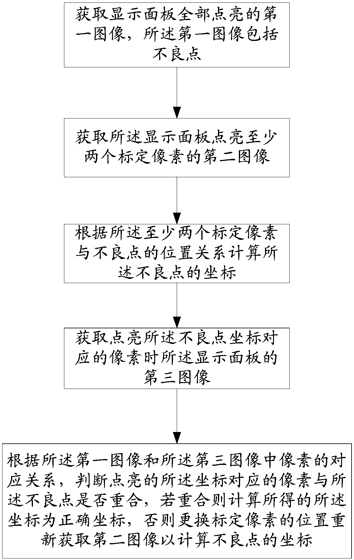
[0032] Please refer to figure 1 , the present embodiment provides a method for automatic detection of bad point coordinates, comprising the following steps:

[0033] Acquiring a first image in which the display panel is fully lit, the first image including defective spots;

[0034] Acquiring a s...


PUM


Abstract

The application discloses a method and device for automatically detecting bad point coordinates, a device and storage medium. The method comprises following steps: obtaining a first image in which theoverall display panel is lightened, wherein the first image comprises a bad point; obtaining a second image of the display panel where at least two calibration pixels on the display panel are lightened; calculating the coordinates of the bad point based on the positional relationship between at least two calibration pixels and the bad point; obtaining a third image of the display panel when the pixel corresponding to the coordinates of the bad point is lightened; determining whether the pixel corresponding to the lit coordinates coincide with the bad point according to the correspondence relationship between the pixels in the first image and the third image. The technical solution of the present application performs intelligent addressing calculation of the coordinates of the bad points by using the images where plurality of calibration pixels are lit, and compares with the acquired images to achieve accurate automatic addressing of the coordinates of the bad points. The invention canautomatically determine the position of the bad point, reduce the steps of the operation and the artificial operation, save the human resources and improve the correct rate of the bad point determination.

Description

technical field [0001] The present disclosure generally relates to the field of display panels, and in particular, relates to a method and device, device, and storage medium for automatic detection of defective point coordinates. Background technique [0002] After the LCD panels are boxed, box inspection is required. The main purpose of the test is to detect defects in the process, so as to prevent defective panels from being put into the post-process and reduce the waste of assets in the post-project. In order to facilitate lighting and save costs, the high-resolution product design uses the Shorting Bar method to conduct a Cell Test test. A Shorting Bar test to intercept defective panels requires a second Full Contact test to report the coordinates, perform repairs based on the defective coordinates, and perform three Full Contact tests to confirm the repair effect. Driven by Industry 4.0, a Shorting Bar test has been automated and unmanned. Since one Shorting Bar test ...

Claims


Application Information

Patent Timeline
IPC IPC(8): G02F1/13
CPCG02F1/1309
Inventor 张小明李世军樊宇驰吴佳伟吴恒张军盛化鹏
Owner BOE TECH GRP CO LTD
Why Eureka
Try Eureka