ed core protection device and LCD screen light alignment equipment analyzer module
A protection device and core technology, which is applied in the measurement device, the polarization of the measurement light, optics, etc., can solve the problems of no internal heat dissipation design, large temperature fluctuation under strong light working conditions, and excessive light incident angle range. Easy to disassemble and maintain, improve measurement efficiency and accuracy, and improve the effect of measurement accuracy
- Summary
- Abstract
- Description
- Claims
- Application Information
AI Technical Summary
Problems solved by technology
Method used
Image
Examples
Embodiment 1
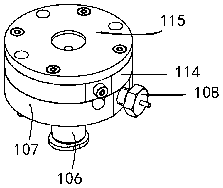
[0052] Such as Figure 3 to Figure 5 As shown, the ED core protection device of this embodiment includes: a pipe joint 106 , a support 107 , a temperature sensor 108 , an ED core 109 , a core cover 114 , an air cavity cover 115 and a tightening screw 113 .
[0053] Continue to refer to Figure 3 to Figure 5, the support member 107 is provided with a core wiring chamber 118, an outlet hole and a pipe joint installation interface. Specifically, the pipe joint 106 is fixedly connected to the support 107 through the pipe joint installation interface, so that the external compressed gas or other cooling gas is passed into the core wiring chamber 118, and the ED core The body 109 is arranged on the surface of the support member 107, and has a chip protection plastic shell and a protective glass on it. The core cover plate 114 is provided with a circumferential positioning boss, which cooperates with the tightening screws 113 arranged around the circumferential positioning boss to ...
Embodiment 2
[0069] The main difference between this embodiment and Embodiment 1 is that: the structure of the heat dissipation channel in the ED core protection device is different. The difference between this embodiment and Embodiment 1 will be mainly explained below.
[0070] Such as Figure 6-7 As shown, the ED core protection device of this embodiment includes an air cavity cover 115, a core cover 114 and a support 107 arranged sequentially from top to bottom, and the ED core 109 is arranged on the core cover 114, and is supported horizontally by the first baffle plate 121 and the second baffle plate 122 matched with the core cover plate 114; The air intake chamber 123 inside 107 is communicated; further, the core body cover plate 114 is provided with a core wiring chamber 118 communicated with the air intake chamber 123 .
[0071] Therefore, the flow direction of the heat dissipation gas in the heat dissipation channel in this embodiment is: compressed gas or other cooling gas enter...
Embodiment 3
[0074] The difference between this embodiment and Embodiments 1 and 2 lies in that the structure of the heat dissipation channel in the ED core protection device is different. The difference between this embodiment and Embodiments 1 and 2 will be mainly explained below.
[0075] Such as Figure 8 to Figure 10 As shown, the ED core protection device of this embodiment includes a core cover plate 114, a support member 107 and a bottom plate 124 arranged sequentially from top to bottom, wherein the ED core 109 is arranged on the surface of the support member 107 and Fixed by the core cover plate 114 , the pipe joint 106 is arranged at the bottom of the bottom plate 124 , and the temperature sensor 108 is installed on the side of the bottom plate 124 , the support member 107 or the core cover plate 114 .
[0076] The heat dissipation channel of the ED core protection device includes: the air inlet chamber 123 formed by the base plate 124 and the support member 107 and the core wir...
PUM
 Abstract
Description
Claims
Application Information
 - R&D
- Intellectual Property
- Life Sciences
- Materials
- Tech Scout
- Unparalleled Data Quality
- Higher Quality Content
- 60% Fewer Hallucinations
Browse by: Latest US Patents, China's latest patents, Technical Efficacy Thesaurus, Application Domain, Technology Topic, Popular Technical Reports.
© 2025 PatSnap. All rights reserved.Legal|Privacy policy|Modern Slavery Act Transparency Statement|Sitemap|About US| Contact US: help@patsnap.com


