Load state detection method, device and circuit and conditioner controller
A technology of load status detection and electrical appliances, applied in heating and ventilation control systems, heating methods, lighting and heating equipment, etc., can solve problems such as complex components of air-conditioning controllers, inability to accurately locate faults, waste of manpower and material resources, etc. , to achieve the effect of improving the quality of after-sales service, quickly and accurately locating faults, and reducing manpower and material resources
- Summary
- Abstract
- Description
- Claims
- Application Information
AI Technical Summary
Problems solved by technology
Method used
Image
Examples
Embodiment 1
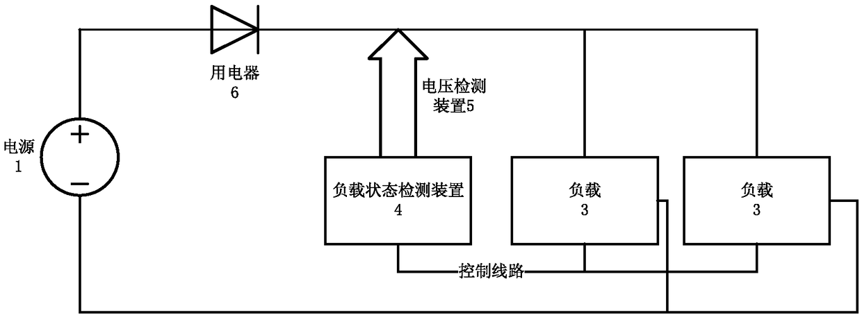
[0126] Figure 5 It is a schematic diagram of some other embodiments of the load state detection method of the present invention. Figure 5 The embodiment adopts such as figure 2 The load status detection circuit shown. Among them, the electric appliance 6 adopts a diode, and the diode is placed on the general circuit of the circuit, and the voltage detection module 5 respectively detects the voltage at both ends of the diode; and the actuator (load 3) is placed in the circuit.
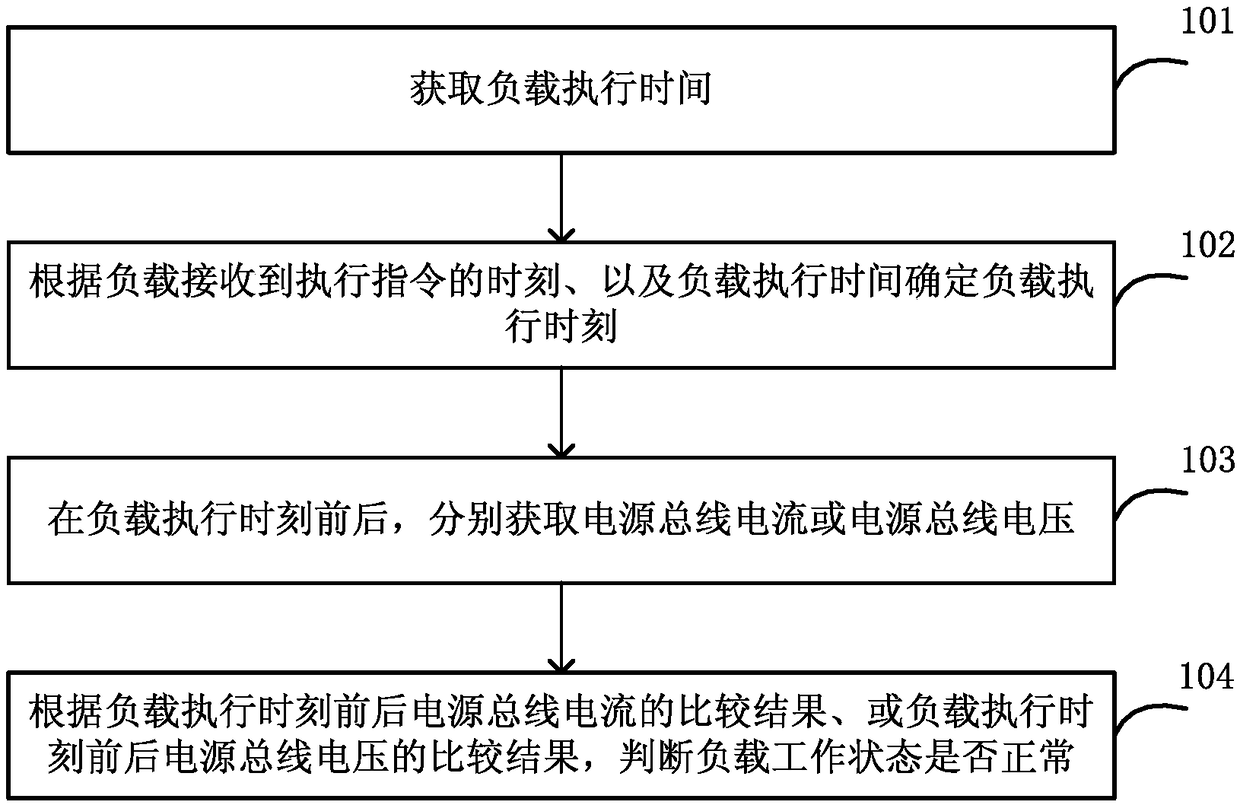
[0127] Such as Figure 5 As shown, the load state detection method may include:
[0128] In step 501, the load state detecting device 4 sends an operation instruction to the load 3 (air conditioner controller device).
[0129] Step 502, after the actuator (load) receives the execution command from the controller, it will take a period of delay T1 before it can act. In the initial working state of the device, its voltage jitter range is large, and the detection is performed immediately at this ti...
Embodiment 2
[0138] In the case that the air conditioner controller includes multiple actuators, since it needs to judge a single actuator, the control method is somewhat different from the traditional control method. Interval control needs to be implemented, that is, only one actuator is executed each time, and the load execution time T1 and load execution time t1 are calculated for the execution time of each actuator, and the predetermined time period T2 before the load execution time t1 and after the load execution time t1 During the predetermined time period T2, the detection circuit judges the bus, and since only one actuator is executed, it can be determined that the actuator is the action when a change is detected. After the predetermined time period T2 after the load execution time t1, the next actuator will perform detection again.
[0139] It can thus be determined that the time T required by the load state detection device to detect an actuator is the sum of the load execution t...
PUM
 Abstract
Description
Claims
Application Information
 - R&D
- Intellectual Property
- Life Sciences
- Materials
- Tech Scout
- Unparalleled Data Quality
- Higher Quality Content
- 60% Fewer Hallucinations
Browse by: Latest US Patents, China's latest patents, Technical Efficacy Thesaurus, Application Domain, Technology Topic, Popular Technical Reports.
© 2025 PatSnap. All rights reserved.Legal|Privacy policy|Modern Slavery Act Transparency Statement|Sitemap|About US| Contact US: help@patsnap.com


