Centrifugal pump enclosed impeller

A pump closed type, impeller technology, applied in the field of centrifugal pumps, can solve the problems of difficult processing, leakage of the sealing ring in front of the impeller, high matching accuracy and clearance requirements, and achieves convenient installation, reduces processing accuracy requirements and assembly accuracy requirements, Simple and efficient production process

Pending Publication Date: 2018-07-27
陈恒平
View PDF11 Cites 0 Cited by
  • Summary
  • Abstract
  • Description
  • Claims
  • Application Information

AI Technical Summary

Problems solved by technology

[0005] For this reason, it is necessary to provide a centrifugal pump closed impeller to solve the problem that the front sealing ring of the impeller of the existing centrifugal pump will leak, and when processing the centrifugal pump, the processing is difficult due to the high requirements for matching accuracy and clearance

Method used


Image

  • Centrifugal pump enclosed impeller
  • Centrifugal pump enclosed impeller
  • Centrifugal pump enclosed impeller

Examples


Embodiment Construction

[0044] In order to explain in detail the technical content, structural features, achieved goals and effects of the technical solution, the following will be described in detail in conjunction with specific embodiments and accompanying drawings.

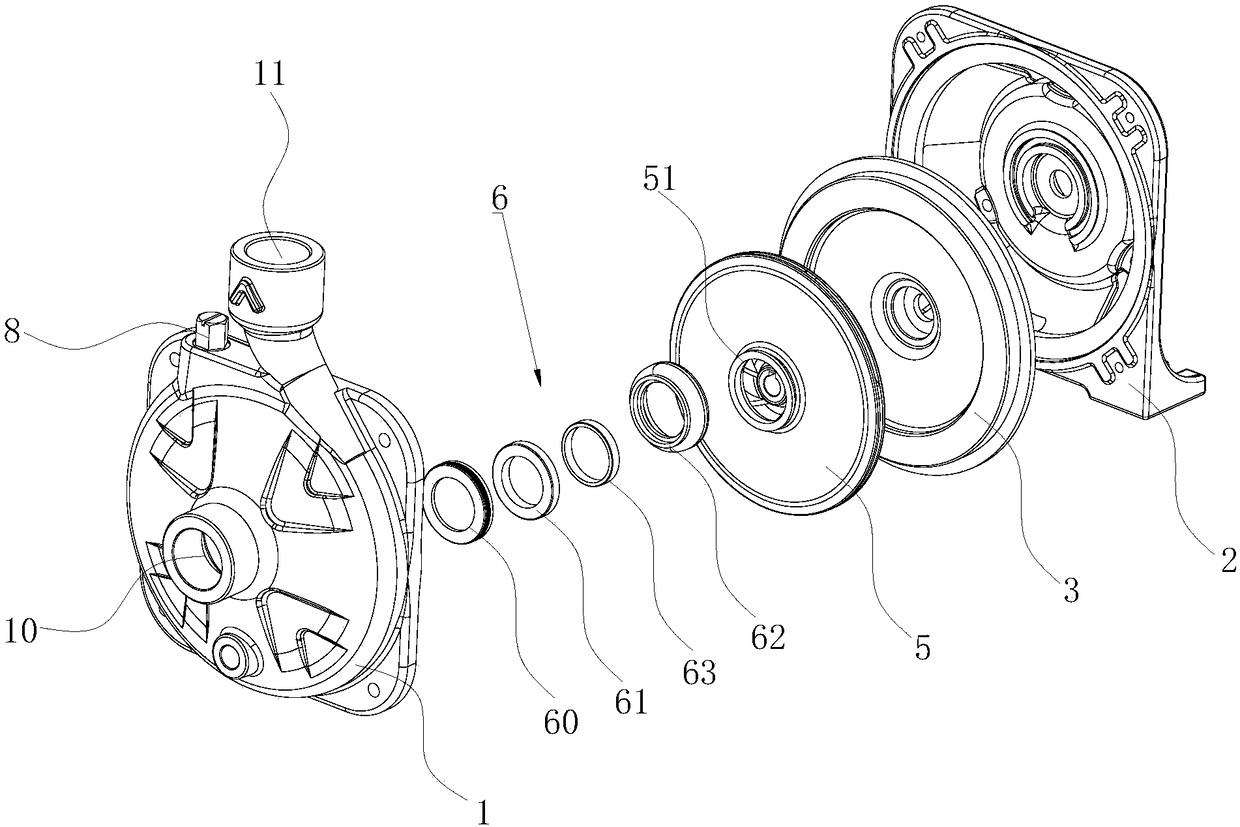
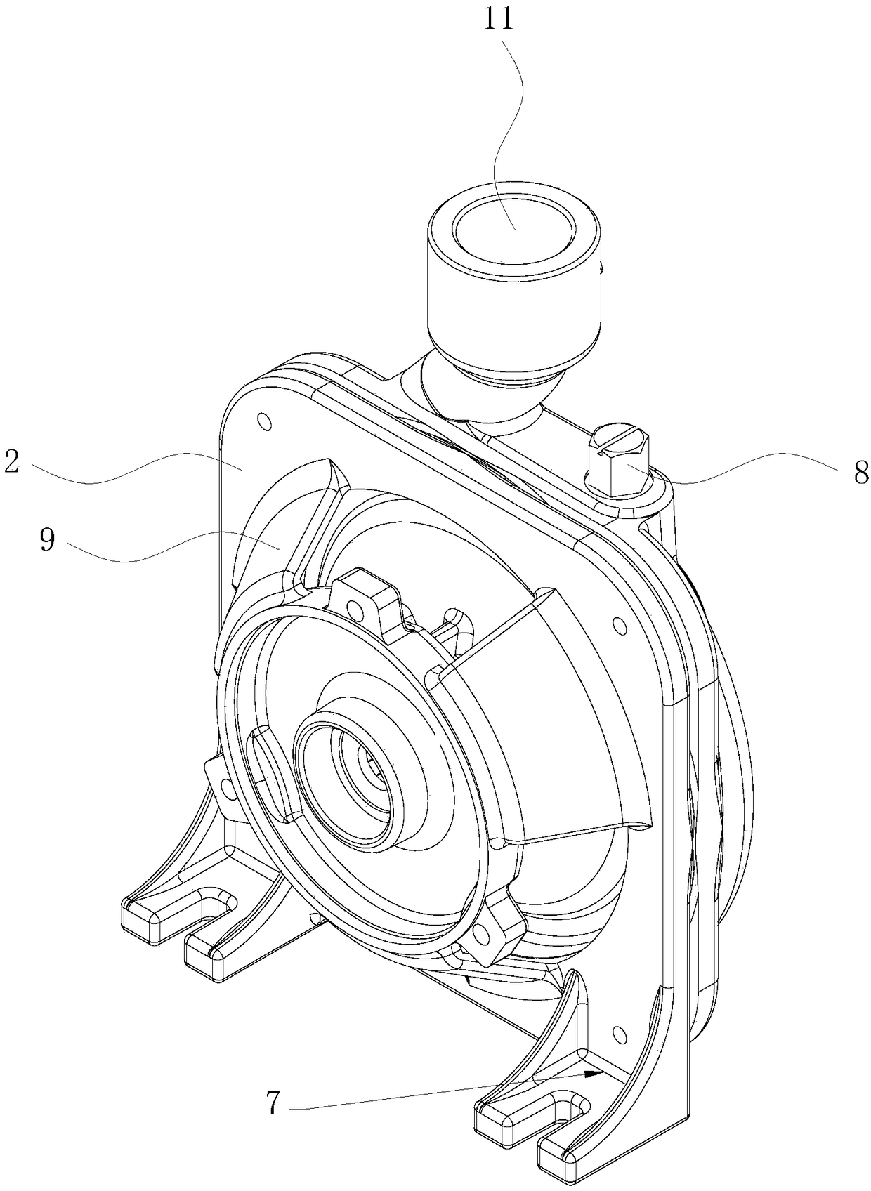
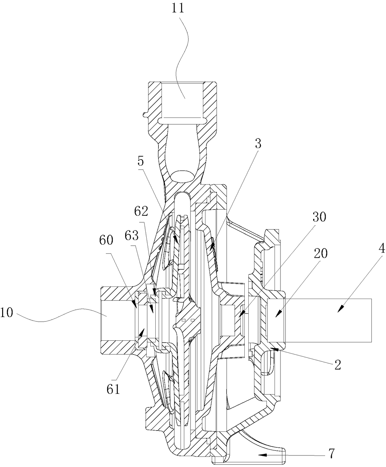
[0045] see figure 1 , figure 2 and image 3 , The invention provides a closed impeller of a centrifugal pump, which is used to provide rotational force for the pump body. The centrifugal pump works by using the impeller to rotate to cause the water to undergo centrifugal motion. Before starting the pump, the pump casing and the suction pipe must be filled with water, and then the motor is started, so that the pump shaft connected to the drive shaft drives the impeller and the water to rotate at a high speed, and the water undergoes centrifugal motion and is thrown to the outer edge of the impeller. The flow channel of the volute pump casing flows into the pressure water pipeline of the water pump.

[0046] In a specific embodiment...


PUM


Abstract

The invention discloses a centrifugal pump enclosed impeller. The centrifugal pump enclosed impeller comprises a pump body, a front cover, a casting iron tray, a drive shaft, an impeller body and a sealing structure, wherein the pump body is arranged on the end surface of the front cover, a first water inlet is formed in the middle of the pump body, a first shaft hole is formed in the middle of the front cover, and the first water inlet and the first shaft hole are coaxial; the sealing structure comprises a rubber part, a graphite sealing ring, a static ceramic ring and a static silica gel ring, the static silica gel ring is arranged at the first water inlet end on the inner side surface of the pump body and sleeved with the static ceramic ring, the casting iron tray is arranged between the pump body and the front cover, the impeller body is arranged between the casting iron tray and the pump body, and the peripheral side of the casting iron tray is clamped at the joint of the pump body and the front cover; the rubber part is arranged at a second water inlet of the impeller body in a sleeving manner, sleeved with the graphite sealing ring and propped against the static ceramic ring. The centrifugal pump enclosed impeller has the advantages of preventing leakage and improving overall efficiency.

Description

technical field [0001] The invention relates to the field of centrifugal pumps, in particular to a closed impeller of a centrifugal pump. Background technique [0002] Centrifugal pumps work by rotating the impeller to cause the water to move centrifugally. Before the pump is started, the pump casing and the suction pipe must be filled with water, and then the motor is started, so that the pump shaft drives the impeller and the water to rotate at a high speed. The pressure water line flowing into the water pump. [0003] The inlet fit of the closed impeller of the existing centrifugal pump is a clearance fit, and the matching structure of the impeller front seal ring and the pump body is an overlapping clearance fit. There is a certain gap, which will cause the liquid to leak through the gap when the centrifugal pump is running, and then The volumetric efficiency of the centrifugal pump is reduced. Since the leakage of liquid will increase with the increase of the matchin...

Claims


Application Information

Patent Timeline
IPC IPC(8): F04D29/16F04D29/22
CPCF04D29/167F04D29/22
Inventor 刘冰农亦华陈恒平
Owner 陈恒平
Why Eureka
Try Eureka