Retaining wall structure used for civil construction and construction method thereof

A technology for civil construction and retaining walls, applied in infrastructure engineering, buildings, underwater structures, etc., can solve problems such as weak water pipe systems, low service life, and affecting pedestrians' driving, and achieve good promotion and practical value. Guarantee the effect of unimpeded driving on the road surface and passers-by

Active Publication Date: 2018-07-27
CHINA CONSTR SECOND ENG BUREAU LTD
View PDF12 Cites 0 Cited by
  • Summary
  • Abstract
  • Description
  • Claims
  • Application Information

AI Technical Summary

Problems solved by technology

[0004] The purpose of the present invention is to provide a retaining wall structure for civil construction and its construction method, to solve the technical problem that the vegetation will grow too vigorously in the prior art, and the vegetation will affect the driving of passersby when the vegetation climbs to the road surface; The system is not strong and the technical problem of low service life

Method used


Image

  • Retaining wall structure used for civil construction and construction method thereof
  • Retaining wall structure used for civil construction and construction method thereof
  • Retaining wall structure used for civil construction and construction method thereof

Examples


Embodiment Construction

[0031] In order to make the technical means, innovative features, goals and effects achieved by the present invention easy to understand, the present invention will be further described below.

[0032] The examples described here are specific specific implementations of the present invention, and are used to illustrate the concept of the present invention. They are all explanatory and exemplary, and should not be construed as limiting the implementation of the present invention and the scope of the present invention. In addition to the embodiments described here, those skilled in the art can also adopt other obvious technical solutions based on the claims of the application and the contents disclosed in the description, and these technical solutions include adopting any obvious changes made to the embodiments described here. Replacement and modified technical solutions.

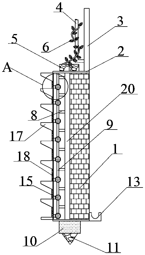
[0033] A retaining wall structure for civil construction, such as figure 1 As shown, the retaining wall b...


PUM


Abstract

The invention discloses a retaining wall structure used for civil construction and a construction method thereof. The retaining wall structure comprises a retaining wall body; the retaining wall bodycomprises a soil-front-side wall plate, a soil-back-side wall plate and a wall body bottom plate which is arranged between the soil-front-side wall plate and the soil-back-side wall plate; a pre-buried block and a deep-buried block are sequentially arranged on the bottom of the wall body bottom plate from top down; a drainage ditch which extends longitudinally along the retaining wall body is arranged at the outside wall corner of the soil-back-side wall plate; a cover plate is arranged on the retaining wall body; a wall pressing top stone is arranged on the cover plate; a retaining plate is arranged on the cover plate and is vertically arranged; the retaining plate extends in the longitudinal direction of the retaining wall body; the plane on which the outside plate surface of the retaining plate is flash to the plane on which the outside plate surface of the soil-back-side wall plate; an L-shaped plant climbing rod is arranged on the inner side plate surface of the retaining plate; the horizontal part of the L-shaped plant climbing rod is fixedly connected with the retaining plate; plants are wound on the L-shaped plant climbing rod; and a water drainage system and a cement wallplate are arranged in the retaining wall body. The retaining wall structure has very good promotion and application value, and can generate good economic benefits after being widely promoted and applied.

Description

technical field [0001] The invention belongs to the field of retaining wall construction, and in particular relates to a retaining wall structure for civil construction and a construction method thereof. Background technique [0002] The retaining wall refers to the structure that supports the subgrade filling or hillside soil and prevents the deformation and instability of the filling or soil. In the cross section of the retaining wall, the part that is in direct contact with the supported soil is called the back of the wall. The part opposite to the back of the wall and facing the sky is called the wall surface, the part directly in contact with the foundation is called the base, the top surface of the wall opposite to the base is called the top of the wall, the front end of the base is called the wall toe, and the back end of the base is called the wall toe. For the wall heel. [0003] However, the retaining wall structures currently on the market for civil construction ...

Claims


Application Information

Patent Timeline
Patent Type & Authority Applications(China)
IPC IPC(8): E02D29/02A01G9/12
CPCA01G9/12E02D29/02E02D29/0266
Inventor 郭文强任河滨张石林
Owner CHINA CONSTR SECOND ENG BUREAU LTD
Why Eureka
Try Eureka