
Area array laser radar and mobile platform

A technology of laser radar and area array, applied in the field of artificial intelligence, can solve the problems of non-uniform coverage of the measurement area, mismatch of area array photoelectric chips, complex light scanning structure, etc., to improve measurement accuracy and efficiency, and facilitate large-scale Mass production, clear and accurate effect of photoelectric signal

Pending Publication Date: 2018-07-24
BENEWAKE BEIJING TECH CO LTD
View PDF8 Cites 14 Cited by
  • Summary
  • Abstract
  • Description
  • Claims
  • Application Information

AI Technical Summary

Problems solved by technology

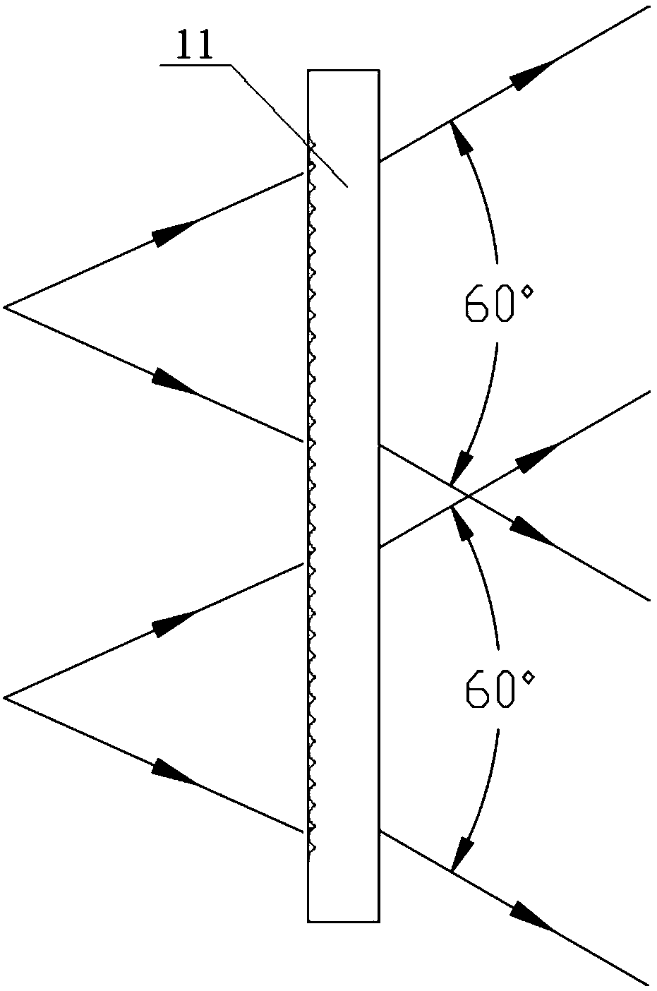
[0005] The purpose of the embodiments of the present invention is to propose a transmitting lens, which solves the problems of complex light scanning structure and low refresh frequency of the mechanical laser radar through the structural setting of the cylindrical lens, and the problem that the transmitting beam of the transmitting system of the ordinary area array laser radar is not stable. uniform problem
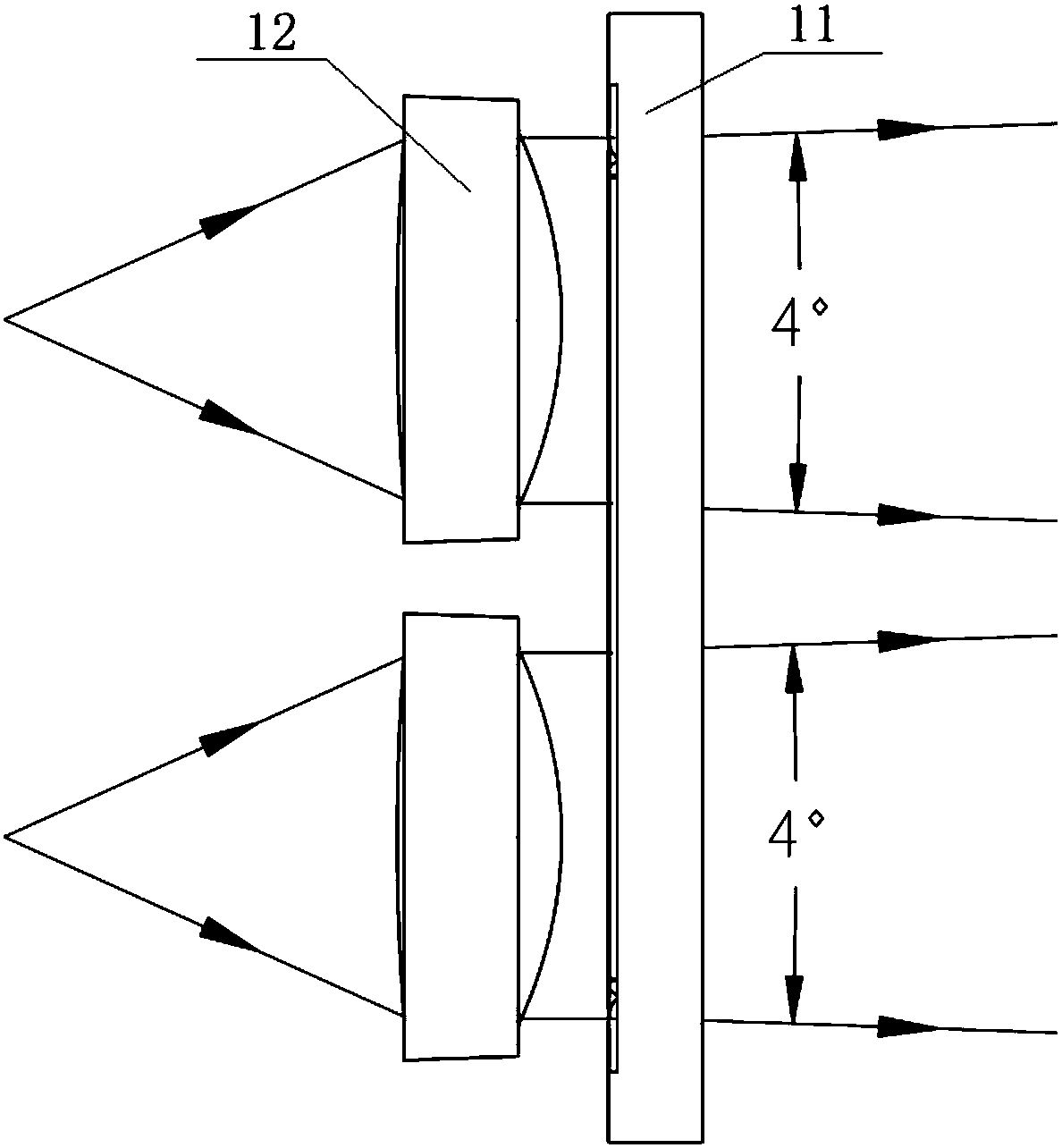
[0006] The purpose of the embodiment of the present invention is also to propose an area array laser radar, through the cooperative setting of the emitting lens and the area array photoelectric chip, it solves the problem that the light beam emitted by the emitting light source in the prior art does not match the area array photoelectric chip after passing through the emitting lens, The problem of non-uniform coverage of the measurement area

Method used


Image

  • Area array laser radar and mobile platform
  • Area array laser radar and mobile platform
  • Area array laser radar and mobile platform

Examples


Embodiment Construction

[0046] The technical solutions of the present invention will be further described below in conjunction with the accompanying drawings and through specific implementation methods.

[0047] It should be noted that, in the case of no conflict, the embodiments in the present application and the features in the embodiments can be combined with each other. The present invention will be described in detail below with reference to the accompanying drawings and examples.

[0048] In order to enable those skilled in the art to better understand the solution of the present application, the technical solution in the embodiment of the application will be clearly and completely described below in conjunction with the accompanying drawings in the embodiment of the application. Obviously, the described embodiment is only It is an embodiment of a part of the application, but not all of the embodiments. Based on the embodiments in this application, all other embodiments obtained by persons of ...


PUM


Abstract

The invention relates to an area array laser radar and a mobile platform. An emission lens comprises an optical reshaping structure arranged in a light emission direction of an emission light source,wherein the optical reshaping structure comprises at least one columnar lens; a length direction of a columnar bulge arranged on one side, close to the emission light source, of each columnar lens isperpendicular to a divergence direction of an emission beam; and the emission beam is a uniform beam with a set divergence angle and a set shape after passing through the optical reshaping structure.The invention further provides the area array laser radar which comprises an area array light emission mechanism, an area array light receiving mechanism and a master control board, wherein the area array light emission mechanism comprises an emission light source, a driving emission circuit and the emission lens. The invention further provides the mobile platform. The problem of the nonuniform emission beam of an emission system of the common area array laser radar is solved, and the testing and operating safety and accuracy are improved.

Description

technical field [0001] The invention relates to the technical field of artificial intelligence, in particular to a transmitting lens, an area array laser radar and a mobile platform. Background technique [0002] LiDAR (Light Detection and Ranging) is the abbreviation of light detection and ranging system. LiDAR is an active distance detection device that uses lasers or LEDs as the emission light source and photoelectric detection technology. Lidar is an advanced detection method combining laser technology and modern photoelectric detection technology. It is mainly composed of transmitting system, receiving system, information processing and other parts. The transmitting system includes various forms of lasers or LEDs; the receiving system uses receiving lenses and various forms of photodetectors. [0003] The commonly used transmitting modules in mechanical rotating lidar are line beams, which are then mechanically rotated to realize area array scanning. This puts high d...

Claims


Application Information

Patent Timeline
Patent Type & Authority Applications(China)
IPC IPC(8): G01S7/481
CPCG01S7/4814G01S7/4817
Inventor 王婷疏达李远张东虎王瑞
Owner BENEWAKE BEIJING TECH CO LTD
Learn More