A kind of magnetron sputtering optical coating equipment and coating method

A magnetron sputtering and optical coating technology, applied in sputtering coating, vacuum evaporation coating, ion implantation coating, etc., can solve the problems of less coating, not suitable for large-scale production, and low efficiency of target coating

Active Publication Date: 2020-03-27
沈阳中北真空技术有限公司
View PDF8 Cites 0 Cited by
  • Summary
  • Abstract
  • Description
  • Claims
  • Application Information

AI Technical Summary

Problems solved by technology

There are also magnetron sputtering optical coating equipment and magnetron sputtering optical coating methods on the market, basically all of which are applied to decoration or mold coating equipment and coating methods, or applied to solar or display device functional magnetron sputtering All of these films do not require precise control of film thickness, and there are few coatings; because the magnetron sputtering optical coating used in the field of optical and electronic devices is to precisely control the coating of multi-layer films under high-speed rotation, the highest coating needs Hundreds of layers of film achieve optical purposes by controlling the passage or reflection of light of different wavelengths; although there are technologies that can be coated with optical films, there are two major problems. The first is that the thickness of the coating cannot be monitored and controlled. Control the time and indirectly control the film thickness; secondly, only oxide targets can be used to directly coat metal oxides. Such targets have extremely low coating efficiency and are not suitable for mass production; therefore, it is necessary to develop magnetic materials suitable for mobile phones and other electronic equipment applications. Sputtering optical coating equipment and vacuum magnetron sputtering coating method applied in optical field

Method used


Image

  • A kind of magnetron sputtering optical coating equipment and coating method
  • A kind of magnetron sputtering optical coating equipment and coating method
  • A kind of magnetron sputtering optical coating equipment and coating method

Examples


Embodiment Construction

[0029] Several magnetron sputtering optical coating devices and magnetron sputtering optical coating methods involved in the present invention are described in conjunction with the accompanying drawings.

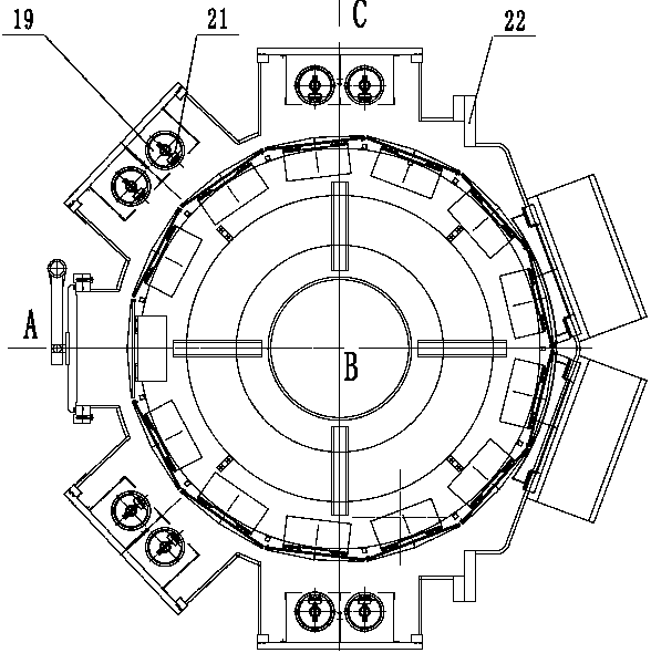
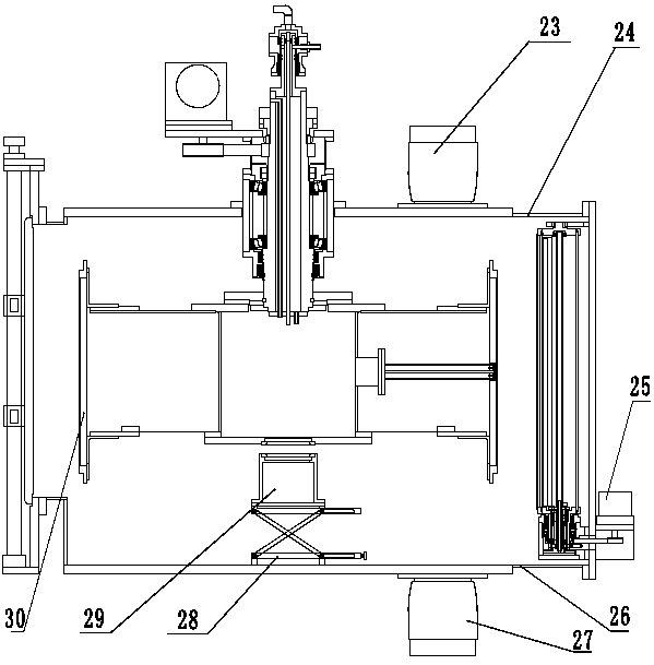
[0030] Such as Figures 1 to 3 As shown, a magnetron sputtering optical coating equipment includes a vacuum coating chamber 3, a magnetron sputtering target assembly 19, and a vertical rotating drum 1; the vacuum coating chamber 3 is a vertical cylindrical structure, and the upper and lower ends are provided with The upper cover plate 24 and the lower cover plate 26 have a side door 22 on the side; the vertical rotary drum 1 is located in the vacuum coating chamber 3 and rotates around the vertical axis. The base plate 30, the center of the vertical rotating drum 1 is provided with a rotary sealing box 10, the top of the rotary sealing box 10 is connected with a rotating shaft 5, and the rotating shaft 5 is supported on the upper cover plate 24 of the vacuum coating chamber ...


PUM

PropertyMeasurementUnit
thicknessaaaaaaaaaa

Abstract

The invention discloses magnetron sputtering optical film plating equipment and a film plating method. The magnetron sputtering optical film plating equipment comprises a vacuum film plating chamber,a plurality of magnetron sputtering target assemblies, and a vertical rotary drum, wherein the vacuum film plating chamber is of a vertical cylinder structure; the vertical rotary drum is positioned in the vacuum film plating chamber, and is rotated around the vertical axis; a rotary sealing box is arranged at the center of the vertical rotary drum, and a film thickness measuring gauge is arrangedin the rotary sealing box; the upper part of the rotary sealing box is connected with a rotary shaft; the atmosphere in the rotary sealing box is separated from the vacuum film plating chamber; the multiple magnetron sputtering target assemblies are arranged at the side wall of the vacuum film plating chamber at the periphery of the vertical rotary drum. The film plating method comprises the following steps of clamping a tooling requiring film plating into the side surface of the vertical rotary drum of the film plating equipment, and sucking the vacuum of the film plating equipment; rotatingthe vertical rotary drum to reach the setting rotation speed; starting a radio frequency ion source; alternatively starting a magnetron target of a first material and a magnetron target of a second material, and plating a film layer according to technology requirements.

Description

technical field [0001] The invention belongs to the field of vacuum equipment, in particular to a magnetron sputtering optical coating equipment and a magnetron sputtering optical coating method applied in the field of optical and electronic devices. Background technique [0002] At present, the main coating equipment for optics and other coatings that require high film thickness accuracy is mainly vacuum evaporation coating. With the development of electronic equipment such as mobile phones, high control precision of the film system is required, as well as large production capacity and low cost. There are also magnetron sputtering optical coating equipment and magnetron sputtering optical coating methods on the market, basically all of which are applied to decoration or mold coating equipment and coating methods, or applied to solar or display device functional magnetron sputtering All of these films do not require precise control of film thickness, and there are few coatin...

Claims


Application Information

Patent Timeline
Patent Type & Authority Patents(China)
IPC IPC(8): C23C14/35C23C14/54
CPCC23C14/0036C23C14/352C23C14/546
Inventor 孙宝玉陈晓东杨威力段永利
Owner 沈阳中北真空技术有限公司
Why Eureka
Try Eureka