Multifunctional paraxial unipod

A monopod, multi-functional technology, applied in the direction of machine/support, optics, instruments, etc., can solve the problems of difficult height adjustment, inability to quickly adjust camera height, easy sliding, etc.

Inactive Publication Date: 2018-07-20
陈义林
View PDF5 Cites 2 Cited by
  • Summary
  • Abstract
  • Description
  • Claims
  • Application Information

AI Technical Summary

Problems solved by technology

[0002] Existing camera monopods cannot quickly adjust the height of the camera in actual use, and the quick release plate between the camera and the gimbal is easy to loosen, especially when supporting the full-frame body and adding a telephoto lens, the weight is heavy, and it is more difficult to adjust the height. And because the top is heavy, the end of the leg tube is easy to slide when it touches the hard ground.
Photographers are very helpless about this, so far no one has proposed a solution to these problems

Method used


Image

  • Multifunctional paraxial unipod
  • Multifunctional paraxial unipod
  • Multifunctional paraxial unipod

Examples


specific Embodiment approach

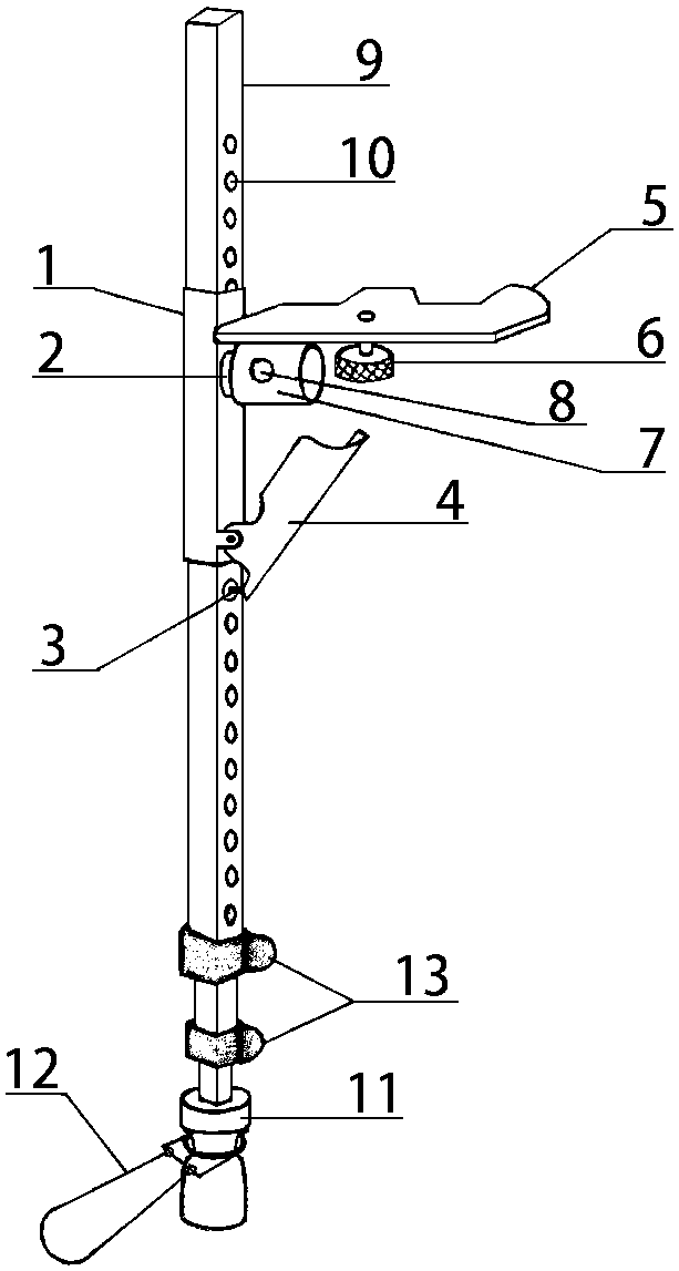
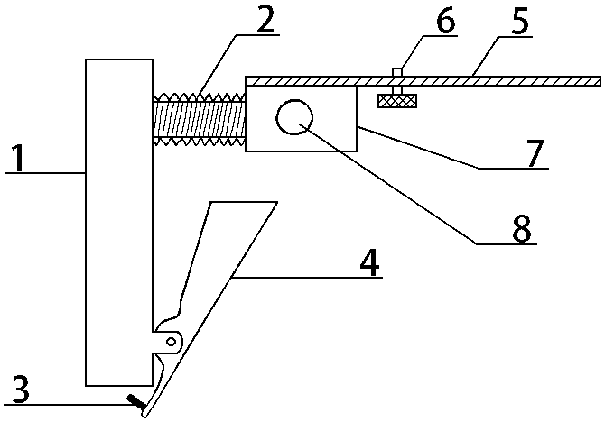
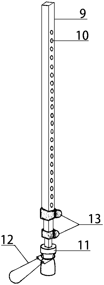
[0005] Specific implementation methods: such as figure 1 As shown, the short sleeve 1 of the camera rangefinder lift bracket is inserted into the support leg 10 with the lift positioning hole 9 to form a multifunctional rangefinder monopod. like figure 2 As shown, the camera paraxial lifting bracket is characterized in that a cross arm 2 with external threads is vertically fixed on the top of the short sleeve 1, and a camera support plate 4 is fixed above the cross arm nut 3 matched with the cross arm 2. There is a camera mounting screw 5 on the supporting plate 4, a locking jack screw 6 on the side of the cross arm nut 3, and a positioning pin handle 7 and a positioning pin 8 for adjusting and locking the height of the lifting bracket are installed on the lower part of the short sleeve 1 . Screw the camera support plate 4 and the cross-arm nut 3 into the cross-arm 2 to form a camera lifting bracket. There is damping between the cross-arm 2 and the cross-arm nut 3, and the...


PUM


Abstract

The invention provides a multifunctional paraxial unipod for photography. The multifunctional paraxial unipod is rapid to adjust and steady and reliable to use. The multifunctional paraxial unipod iscomposed of a camera paraxial ascending-and-descending bracket and an extending-and-contracting support foot pipe, wherein the extending-and-contracting support foot pipe is provided with ascending-and-descending locating holes and tread rings. The multifunctional paraxial unipod is characterized in that a short casing pipe of the ascending-and-descending bracket is sleeved with the foot pipe withthe ascending-and-descending locating holes; a user holds the short casing pipe with the left hand and presses a locating pin handle with the finger, and a locating pin is lifted; the ascending-and-descending bracket and a camera are slid up and down to reach proper positions; the handle is released, and the locating pin is automatically inserted into the corresponding ascending-and-descending locating hole under the effect of a spring to lock the height; and a camera carrying plate is rotated, the pitching angle of the camera is adjusted, locking is conducted through a jackscrew, and photographing is conducted. The traditional mode of conducting support and rotation on the camera is changed from the center of the bottom of the camera to one side of the camera, and therefore, the balanceis better. In the adjustment and photographing processes, the user treads on the tread rings, so that stability achieved in the whole working process of integral equipment is improved. When the multifunctional paraxial unipod is needed, vertical photographing can be achieved, and the camera paraxial ascending-and-descending bracket can be rapidly made to break away from the support foot pipe to beindependently used as a camera handle.

Description

technical field [0001] The invention relates to a multifunctional rangefinder monopod for photography. Background technique [0002] Existing camera monopods cannot quickly adjust the height of the camera in actual use, and the quick release plate between the camera and the gimbal is easy to loosen, especially when supporting the full-frame body and adding a telephoto lens, the weight is heavy, and it is more difficult to adjust the height. And because the top is heavy, the end of the leg tube is easy to slide when it touches the hard ground. Photographers are very helpless about this, and no one has proposed a solution to these problems so far. Contents of the invention [0003] The purpose of the present invention is to provide a new concept of multi-functional rangefinder monopod for photography in view of the above problems, which is composed of a camera lifting bracket and a telescopic support leg tube with a lifting positioning hole and a pedal ring. The camera lif...

Claims


Application Information

Patent Timeline
IPC IPC(8): F16M11/28G03B17/56
CPCG03B17/561F16M11/28F16M2200/08
Inventor 陈义林
Owner 陈义林
Why Eureka
Try Eureka