
Rotary telescopic combined oil cylinder

A combination of oil cylinder and rotary cylinder technology, applied in mechanical equipment, fluid pressure actuators, etc., can solve the problems of small rotational resistance torque, increased linear movement distance of rack, output torque limitation, etc., to achieve compact layout and wide application range The effect of widening and reducing the weight of the vehicle

Pending Publication Date: 2018-07-20
JIANGSU XCMG CONSTR MASCH RES INST LTD
View PDF5 Cites 4 Cited by
  • Summary
  • Abstract
  • Description
  • Claims
  • Application Information

AI Technical Summary

Problems solved by technology

[0004] This form of combined oil cylinder can realize the function of rotation and expansion, but the rotation resistance torque provided is small, so it can only be used in occasions where the demand for rotation resistance torque is small; the steering is driven by hydraulic oil into the rack hydraulic cylinder, and the hydraulic pressure is pushed The rack piston moves, and the rack drives the gear meshed with it to rotate. When the required rotation angle is large, the linear movement distance of the rack will increase accordingly. The rack and pinion in this form of combined oil cylinder takes up a lot of space. The overall size of the combined oil cylinder will also increase, which cannot meet the requirements of some vehicle working conditions; the output torque of this type of helical oscillating oil cylinder is also limited by the size, which cannot meet the steering requirements of engineering vehicles

Method used


Image

  • Rotary telescopic combined oil cylinder
  • Rotary telescopic combined oil cylinder
  • Rotary telescopic combined oil cylinder

Examples


Embodiment 1

[0032] refer to Figure 4 and Figure 5 , the rotary telescopic combination oil cylinder of this embodiment includes a telescopic cylinder 101 and a rotary cylinder 102;

[0033] The telescopic cylinder 101 comprises a first cylinder and a telescopic piston rod 5; in the first cylinder, a rod cavity and a rodless cavity are respectively arranged on both sides of the piston of the telescopic piston rod; The first oil port 11 and the second oil port 12 of the rodless cavity;

[0034] The rotary cylinder 102 includes a second cylinder, a screw piston 7 and a rotary transmission rod 8; one end of the rotary transmission rod 8 is mounted on the cylinder bottom 9 of the rotary cylinder, and the other end penetrates into the inside of the first cylinder; the outer periphery of the screw piston 7 passes through the screw The sleeve 4 is screwed to the inner circumference of the second cylinder, the inner circumference of the screw piston 7 is screwed to the outer circumference of th...


PUM


Abstract

The invention discloses a rotary telescopic combined oil cylinder. The rotary telescopic combined oil cylinder comprises a telescopic cylinder body and a rotary cylinder body; the telescopic cylinderbody comprises a first cylinder barrel and a telescopic piston rod; the rotary cylinder body comprises a second cylinder barrel, a spiral piston and a rotary transmission rod; two oil cavities are arranged in the cylinder barrel of the telescopic cylinder body and the cylinder barrel of the rotary cylinder body respectively, and the cylinder barrels are provided with corresponding oil ports correspondingly; one end of a rotary transmission rod is rotationally installed in the rotary cylinder body, and the other end of the rotary transmission rod penetrates into the interior of the first cylinder barrel; an outer circumferential part of a spiral piston is in threaded connection with an inner circumferential part of the second cylinder barrel, the inner peripheral part is in threaded connection with the rotary transmission rod, and the spiral direction of the outer peripheral part of the spiral piston is opposite to the spiral direction of a spiral line of the inner peripheral part; anda blind hole is formed in the telescopic piston rod, a peripheral part of the hole wall of the blind hole is in transmission connection with the rotary transmission rod through a spline so that the rotary transmission rod can drive the telescopic piston rod to rotate, and the telescopic piston rod can move in the axial direction relative to the rotary transmission rod. According to the rotary telescopic combined oil cylinder, enough steering resistance moment can be provided, steering and suspension expansion can be realized, and meanwhile, the space arrangement of a whole vehicle can be compact.

Description

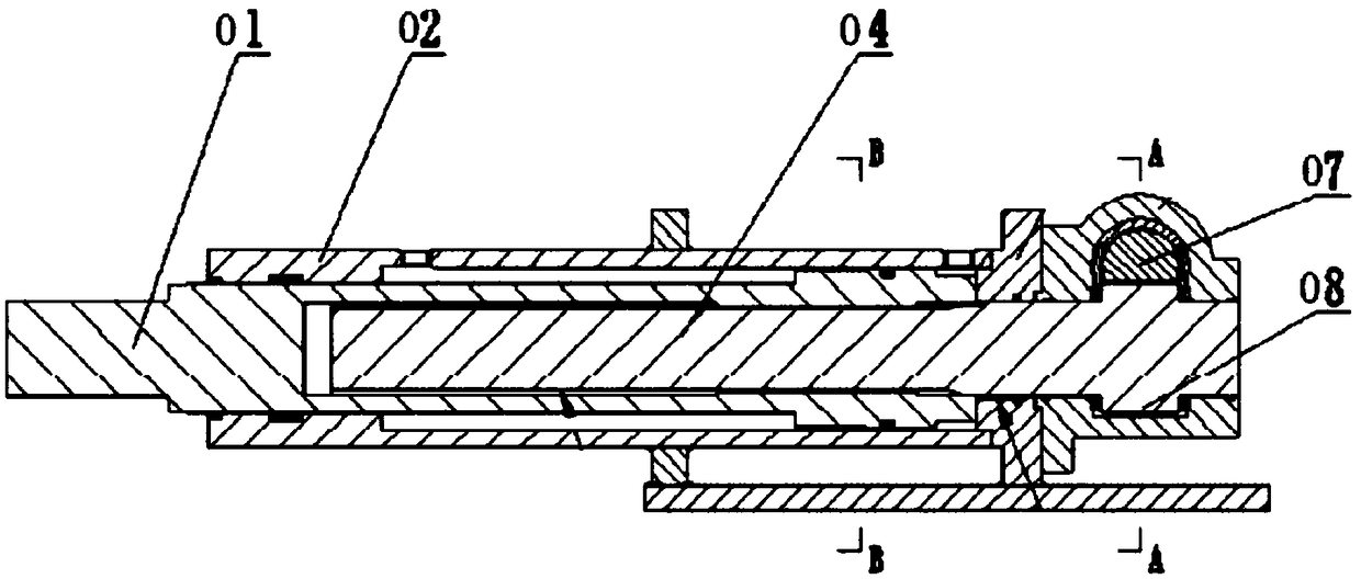
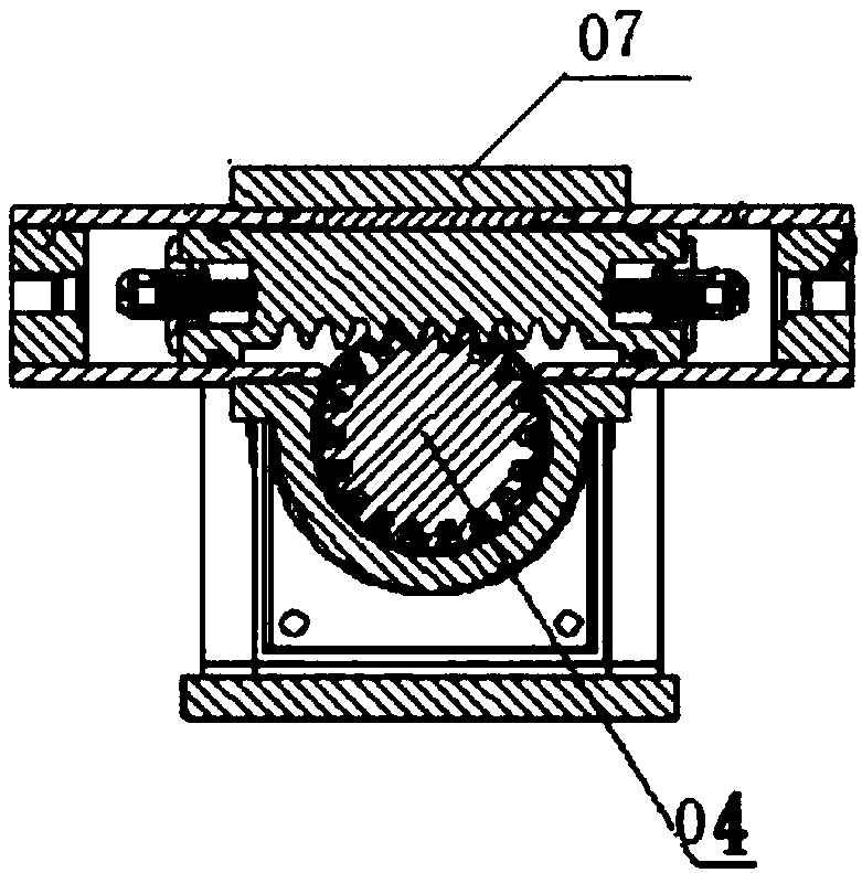
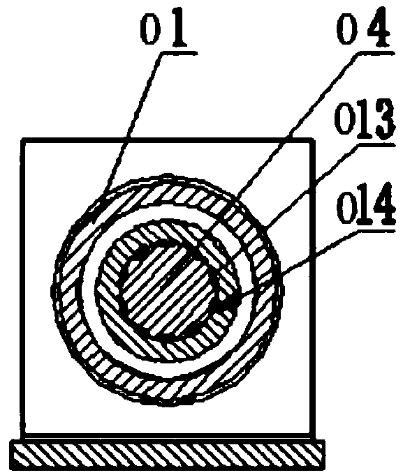
technical field [0001] The invention relates to the technical field of vehicle suspension and steering mechanism design, in particular to a rotary telescopic combined oil cylinder. Background technique [0002] In the field of special vehicle chassis design, because the vehicle suspension cylinder and steering cylinder are arranged at both ends of the axle, the vehicle steering cylinder has a certain swing space, and the suspension cylinder has a certain up and down telescopic stroke, resulting in the space cannot be arranged separately; at the same time, the special vehicle The steering resistance torque is relatively large, and the ordinary rotary cylinder cannot provide the steering resistance torque of the vehicle. [0003] Figure 1 to Figure 3 Shown is a rack and pinion rotary swing oil cylinder disclosed in patent CN106015166A, which drives the rack 07 to move through hydraulic oil, uses the rack 07 to drive the gear shaft 04 to rotate, and the gear shaft 04 drives th...

Claims


Application Information

Patent Timeline
Patent Type & Authority Applications(China)
IPC IPC(8): F15B15/06F15B15/16F15B15/22
CPCF15B15/063F15B15/16F15B15/22F15B2215/30
Inventor 李勇刘帅杰张勇
Owner JIANGSU XCMG CONSTR MASCH RES INST LTD
Learn More