
Mounting frame for a laser measuring instrument

A technology of laser measuring instrument and laser distance measuring instrument, applied in the field of mounting frame, can solve the problems of error efficiency, large vibration, unadjustable mounting frame, etc., and achieve the effect of reducing cost, low cost and compact overall structure

Active Publication Date: 2015-12-02
STATE GRID CORP OF CHINA +1
View PDF7 Cites 0 Cited by
  • Summary
  • Abstract
  • Description
  • Claims
  • Application Information

AI Technical Summary

Problems solved by technology

In the past construction, in order to save costs, most of them used the methods of plumb line alignment, spirit level leveling, manual drawing ruler to measure platform radius, and theodolite to measure platform height. This method has certain errors and low efficiency; some methods use laser plumb instrument, laser rangefinder and laser leveling instrument respectively complete platform centering, leveling, height and radius measurement, which requires a laser instrument installation frame to be set in the center of the platform
And because there are construction equipment such as concrete conveying cages and dismantling pole seats in the center of the platform, the vibration is relatively large during the construction process, and the position of the installation frame cannot be adjusted after being fixed (welded on the steel platform)

Method used


Image

  • Mounting frame for a laser measuring instrument
  • Mounting frame for a laser measuring instrument
  • Mounting frame for a laser measuring instrument

Examples


Embodiment approach

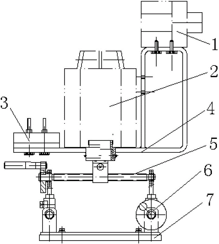
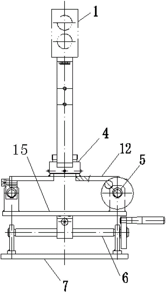
[0026] In another preferred embodiment of the present invention, a lower connecting piece 15 is provided between the axial track 5 and the radial track 6 , and the axial track 5 moves radially on the parallel radial track 6 through the lower connecting piece 15 .

[0027] In another preferred embodiment of the present invention, the lower connecting piece 15 is U-shaped, and the two ends of the lower connecting piece 15 are protruded and fixed to the ends of two parallel axial rails 5, and the cross bar in the middle is connected to the radial rails. The moving blocks on 6 are fixed.

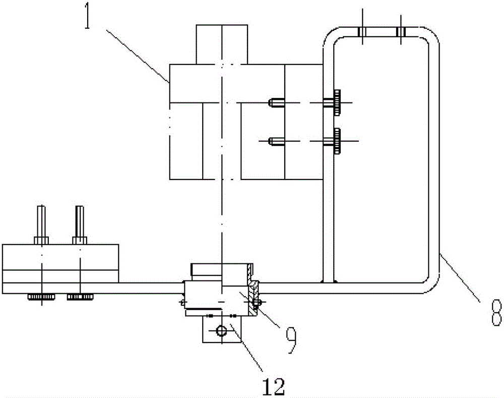
[0028] Such as image 3 and Figure 4 In the shown embodiment, in order to satisfy the horizontal rotation function of the laser rangefinder 1 , a rotation mechanism is provided between the upper connecting member 12 and the bottom plate 4 ; the rotation mechanism enables the bottom plate 4 to rotate horizontally.

[0029] In another preferred embodiment of the present invention, the rotating ...


PUM


Abstract

The invention discloses a laser measuring device installation frame. A laser measuring device comprises a laser swinger and a laser range finder. The laser range finder comprises a range finder outer shell body. A laser emitter and a laser receiver are arranged on the front end portion of the range finder outer shell body, a light reflector mirror, a microcomputer lightning reflecting micromirror and an optical surface mirror are arranged inside the range finder outer shell body, a displaying screen and a voice number reporting device are arranged on the upper surface of the range finder outer shell body, and a compass and a remote positioning device are arranged on the side face of the range finder outer shell body. The installation frame comprises a base plate and a reverse U-shaped support which is arranged at one end of the base plate, a cushion block is arranged at the other end of the base plate, the base plate is movably connected with an axial rail, and the two ends of the axial rail are movably connected with a radial rail. The laser measuring device installation frame is small and exquisite in overall structure, flexible and convenient to operate and low in cost, and has many adjustment functions.

Description

technical field [0001] The invention relates to a mounting frame, in particular to a laser measuring instrument mounting frame. Background technique [0002] The reinforced concrete outer cylinder wall of the chimney of a thermal power plant is generally constructed with a synovial membrane. The bottom diameter of the cylinder can reach 24 meters, the diameter of the cylinder mouth is about 7 meters, and the height is 200-240 meters. During the construction process of up to 2-3 months, the construction platform The cylinder wall rises and gradually reduces the radius. The centering of the platform and the alignment of the radius of the lifting mast are very important in the entire construction process. The deviation of the center and radius is also one of the basis for project quality acceptance. . In the past construction, in order to save costs, most of them used the methods of plumb line alignment, spirit level leveling, manual drawing ruler to measure platform radius, a...

Claims


Application Information

Patent Timeline
Patent Type & Authority Patents(China)
IPC IPC(8): F16M11/20F16M11/04G01B11/02G01C15/00
Inventor 邹玉英布春磊江明
Owner STATE GRID CORP OF CHINA
Learn More