
Air cooling device for tempered glass

A technology of tempered glass and cooling device, applied in the direction of glass tempering, glass manufacturing equipment, manufacturing tools, etc., can solve the problems of stress spots, affecting the appearance of products, stress difference, etc.

Active Publication Date: 2018-07-20
广东天锐节能环保玻璃有限公司
View PDF4 Cites 4 Cited by
  • Summary
  • Abstract
  • Description
  • Claims
  • Application Information

AI Technical Summary

Problems solved by technology

[0004] However, the wind between two adjacent lower air grilles will be blown from the middle to both sides, and the wind generated in the middle part will cool down the glass in contact with the path when it is blown to both sides, and because each section of the lower air grill is blown evenly , the wind blowing near the edge of the lower air grill is also blown to both sides instead of the middle, so that the wind speed at the edge of the lower air grill is greater than the wind speed at the middle part of the lower air grill, and the heat taken away from both sides of the glass is more than that taken away from the middle area. The temperature on both sides of the glass is lower, resulting in a stress difference during cooling, which will form stress spots and affect the appearance of the product

Method used


Image

  • Air cooling device for tempered glass
  • Air cooling device for tempered glass
  • Air cooling device for tempered glass

Examples


Embodiment Construction

[0022] Further detailed explanation through specific implementation mode below:

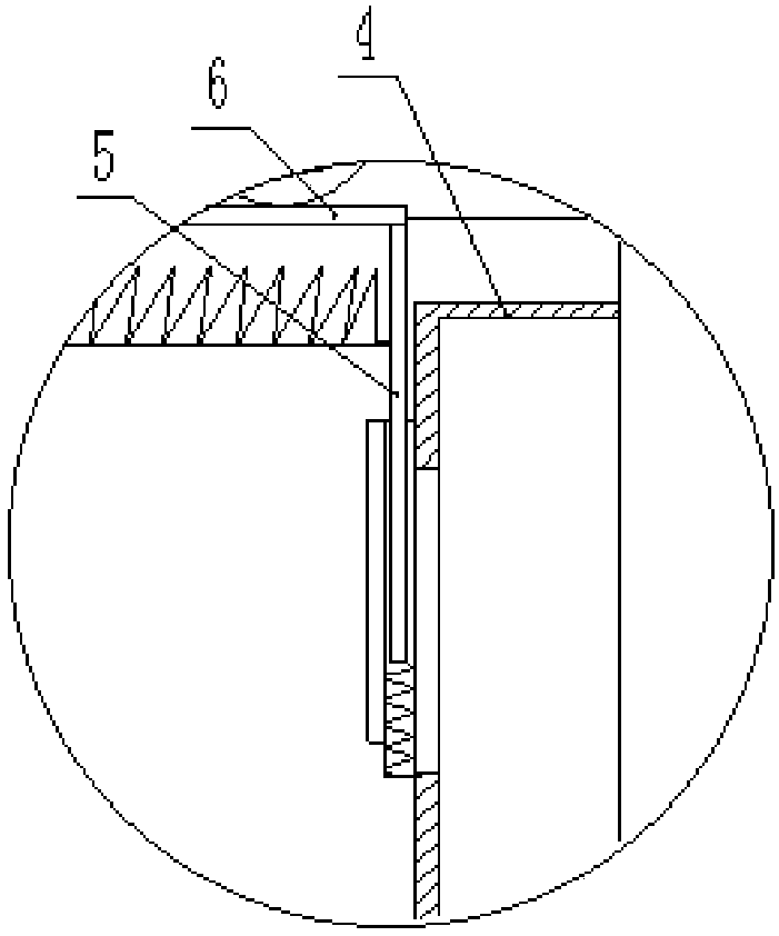
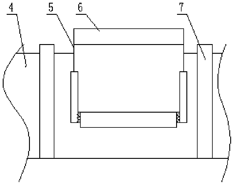
[0023] The reference signs in the drawings of the specification include: upper air grille 1, lower air grille 2, windshield plate 3, exhaust pipe 4, cover body 5, extension body 6, partition plate 7, wind blocking brush 8, wave plate 9 , Drive roller 10, flange 11.

[0024] Such as figure 1 , figure 2 , image 3 , Figure 4 , Figure 5 , Figure 6 As shown, the air-cooled cooling device for tempered glass includes transversely distributed drive rollers 10 , an upper air grille 1 located above the drive rollers 10 and a lower air grille 2 located below the drive rollers 10 . Wherein, the driving roller 10 is arranged vertically, the horizontal direction refers to the driving direction of the driving roller 10 from left to right, and the longitudinal direction refers to the direction perpendicular to the driving direction of the driving roller 10 . The drive roller 10 is wound with an arami...


PUM


Abstract

The invention provides an air cooling device for tempered glass and relates to the field of glass cooling. The air cooling device comprises drive rollers, upper air grids located above the drive rollers and lower air grids located below the drive rollers, wherein an air baffle for preventing air from blowing downwards is arranged below each drive roller and arranged between adjacent lower air grids, a longitudinal exhaust pipe is fixed at the upper end of the air baffle and fixed on the side surface of the corresponding lower air grid, and two ends of the exhaust pipe are open; multiple vertically transverse partitions are arranged on each air baffle longitudinally, so that multiple cooling units which are only open at upper ends are formed by the partitions with the lower air grids, the exhaust pipes and the air baffles; each exhaust pipe is provided with an air inlet in the corresponding cooling unit, and the lower air grids blow glass for cooling; air cushions are formed by air accumulation in each cooling unit, air in the cooling units can be discharged from the exhaust pipes through the air inlets instead of blowing to two sides along the two lower air grids, so that the longitudinal cooling effect on the glass is uniform, and stress difference caused by non-uniform cooling is reduced.

Description

technical field [0001] The invention relates to a glass cooling device, in particular to an air-cooling cooling device for tempered glass. Background technique [0002] Tempered glass is to put ordinary glass into a heating furnace for quenching and softening. After heating, the softened glass is sent to a cooling device for rapid cooling and cooling. At present, the common transmission method is to drive the glass in the cooling device through the transmission roller, and the aramid rope is wound on the transmission roller. Since the transmission roller and the aramid rope have good thermal conductivity, the part of the glass in contact with the transmission roller and the aramid rope is cooled. The faster the speed, the first cooled part will form a greater stress, while the other parts of the glass are cooled by cold air, the glass is cooled slowly, and there is a temperature difference on the glass surface, which causes stress differences on the surface of the tempered g...

Claims


Application Information

Patent Timeline
Patent Type & Authority Applications(China)
IPC IPC(8): C03B27/044
CPCC03B27/044
Inventor 王宏伟
Owner 广东天锐节能环保玻璃有限公司
Learn More