Clamping mechanism

A clamping mechanism and locking sleeve technology, applied in auxiliary devices, auxiliary welding equipment, welding/cutting auxiliary equipment, etc., can solve the problems of increasing the complexity of the tooling mechanism, being unable to install pressure clamps nearby, and increasing the manufacturing cost. It is convenient for unified production and management, convenient for rational use of space, and the effect of improving production efficiency

Inactive Publication Date: 2018-07-20
ANHUI JIANGHUAI AUTOMOBILE GRP CORP LTD
View PDF6 Cites 1 Cited by
  • Summary
  • Abstract
  • Description
  • Claims
  • Application Information

AI Technical Summary

Problems solved by technology

[0004] When the parts to be pressed are large or the structure is complex, the position of the positioning block cannot be installed nearby. At this time, the pressing force of the pressing pliers is too long due to...

Method used


Image

  • Clamping mechanism
  • Clamping mechanism
  • Clamping mechanism

Examples


Embodiment Construction

[0030] The embodiments described below by referring to the figures are exemplary only for explaining the present invention and should not be construed as limiting the present invention.

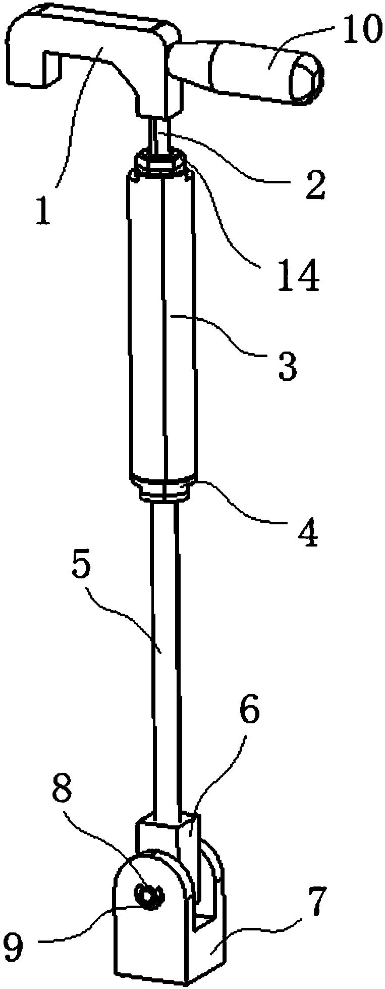
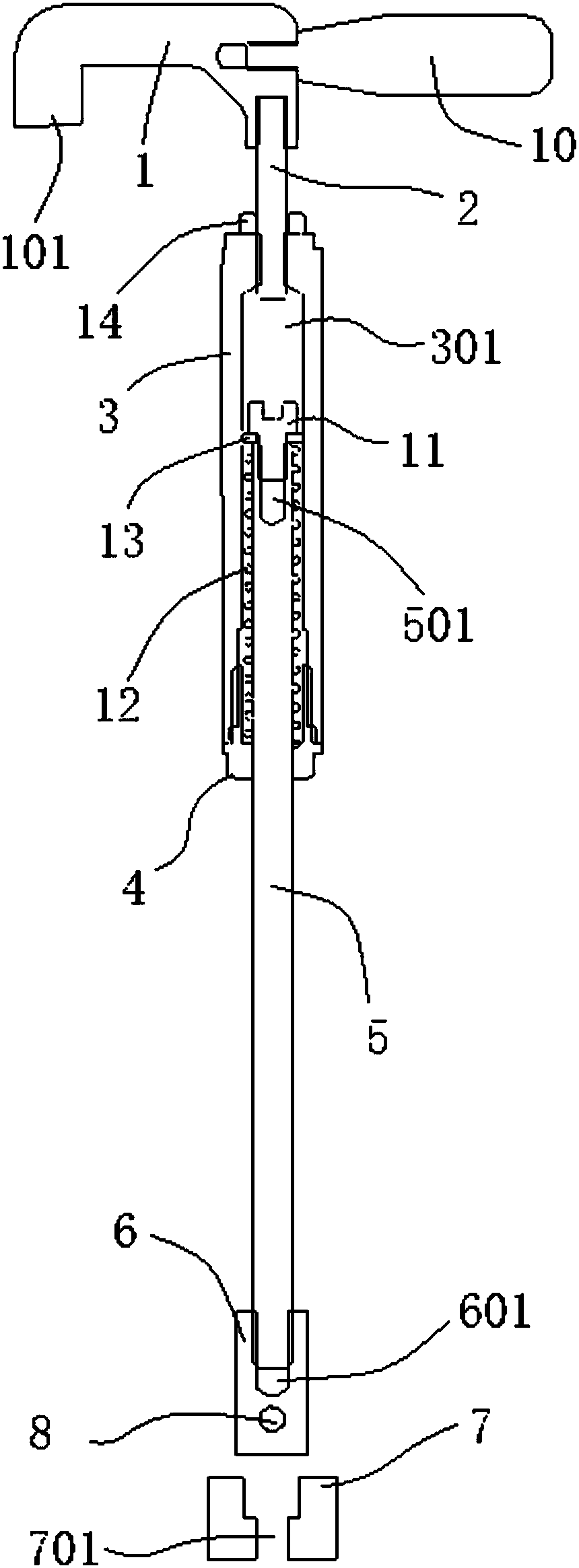
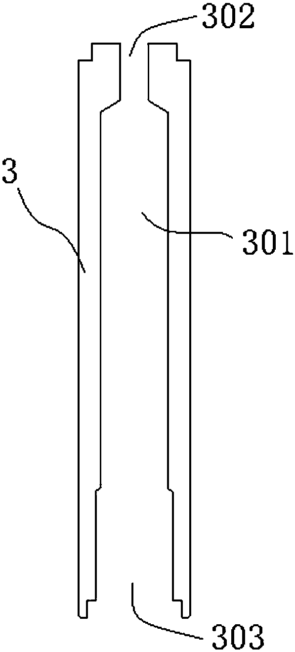
[0031] like figure 1 and figure 2 As shown, the embodiment of the present invention provides a clamping mechanism, including a pressure block 1, a first connecting rod 2, a shaft sleeve 3, a locking sleeve 4, a second connecting rod 5, a connecting block 6, a base 7, a connecting Shaft 8, stretchable elastic part 12 and limit block 13, one end of briquetting block 1 is provided with pressing part 101, the other end of briquetting block 1 is fixedly connected with the top end of first connecting rod 2, the first connecting rod 2 The bottom end is fixedly connected with the top end of the shaft sleeve 3, and the bottom end of the shaft sleeve 3 is fixedly connected with the locking sleeve 4. The inside of the shaft sleeve 3 has a cavity 301, and the inside of the cavity 301 is provided with a...


PUM


Abstract

The invention discloses a clamping mechanism. A compressing portion is arranged at one end of a pressure block; the other end of the pressure block is fixedly connected with the top end of a first connection rod; the bottom end of the first connection rod is fixedly connected with the top end of a shaft sleeve; the bottom end of the shaft sleeve is fixedly connected with a locking sleeve; a cavityis formed in the shaft sleeve; telescopic elastic parts and a limiting blocking piece are arranged inside the cavity; the top end of a second connection rod penetrates through the locking sleeve andis fixedly connected with the limiting blocking piece; the telescopic elastic parts are evenly distributed on the peripheral side of the second connection rod and located between the limiting blockingpiece and the locking sleeve; the second connection rod and the locking sleeve are in sliding fit; the bottom end of the second connection rod is fixedly arranged on a connection block; the connection block is connected with a base through a connection shaft; and the base is provided with a sixth mounting hole used for being connected with an outer structure. The clamping mechanism provided by the invention is small in space occupation, clamping of to-be-compressed boards is achieved by cooperation with lifting of the pressure block and elastic restoring force of the telescopic elastic parts,the conception is exquisite, and operation is flexible.

Description

technical field [0001] The invention relates to a clamp, in particular to a clamping mechanism. Background technique [0002] There are two kinds of fixtures and inspection tools commonly used in the welding of the automobile industry. The fixture is an important tool to ensure that the body-in-white is gradually welded from scattered parts. The inspection tool is an important tool for measuring the accuracy of each component assembly of the body-in-white and evaluating the welding quality. tooling. Both of these two kinds of tooling need to use reasonable positioning and pressing devices to fix the parts for tailor welding or testing. Therefore, the positioning and pressing device is required to be compact in structure and easy to operate, thereby ensuring product processing quality, improving work efficiency, and reducing labor intensity. [0003] In the prior art, the commonly used positioning mechanism adopts a positioning block and a press clamp, and the positioning b...

Claims


Application Information

Patent Timeline
IPC IPC(8): B23K37/04
CPCB23K37/0443
Inventor 王兰梅光磊张宇陈明洁范青山王学敏
Owner ANHUI JIANGHUAI AUTOMOBILE GRP CORP LTD
Why Eureka
Try Eureka