
Radiation source localization system and method

A positioning system and positioning method technology, applied in the field of nuclear radiation detection, can solve the problems of blind detection methods, irradiation, and long process time, and achieve the effects of improving detection sensitivity, expanding positioning field of view, and reducing production costs.

Active Publication Date: 2019-11-05
BEIJING NOVEL MEDICAL EQUIP LTD
View PDF7 Cites 0 Cited by
  • Summary
  • Abstract
  • Description
  • Claims
  • Application Information

AI Technical Summary

Problems solved by technology

[0003] In related technologies, gamma dosimeters or spectrometers are used to search for radioactive sources. However, these detectors do not have the ability to locate directions, and require manual, vehicle-mounted, or airborne methods to carry nuclear radiation detectors to carry out blanket searches, resulting in relatively blind detection methods. , the process takes a long time, reduces the efficiency of radioactive source search, and source search personnel are easily exposed to radioactive source radiation at close range, resulting in additional dose exposure
Although detectors with imaging capabilities such as coded plate imaging detectors, collimators for gamma radiation source locators, and Compton cameras have also been developed, these detectors have low detection sensitivity and high cost

Method used


Image

  • Radiation source localization system and method
  • Radiation source localization system and method
  • Radiation source localization system and method

Examples


Embodiment Construction

[0026] Embodiments of the present invention are described in detail below, and examples of the embodiments are shown in the drawings, wherein the same or similar reference numerals denote the same or similar elements or elements having the same or similar functions throughout. The embodiments described below by referring to the figures are exemplary and are intended to explain the present invention and should not be construed as limiting the present invention.

[0027] The radioactive source locating system and method according to the embodiments of the present invention will be described below with reference to the accompanying drawings. First, the radioactive source locating system according to the embodiments of the present invention will be described with reference to the accompanying drawings.

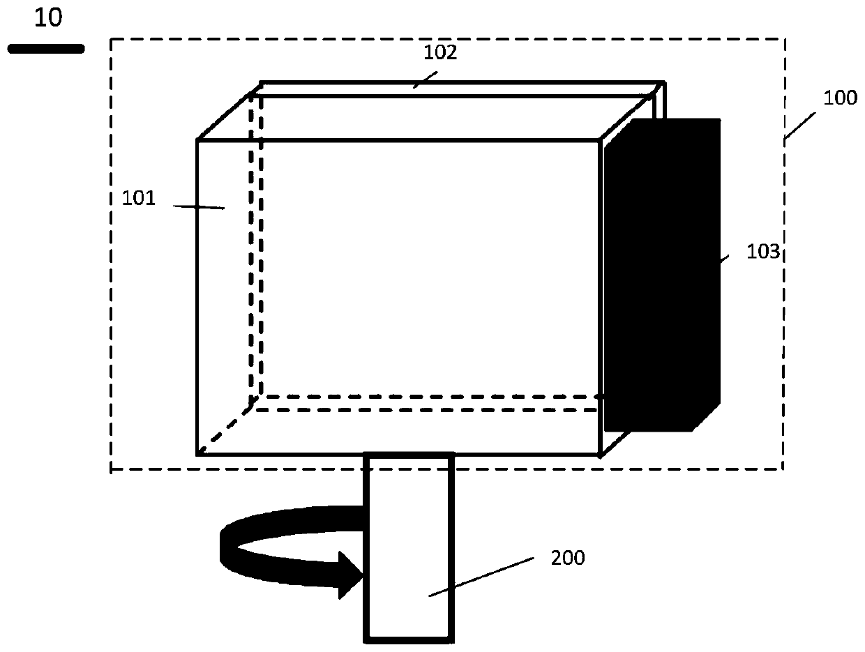
[0028] figure 1 It is a structural schematic diagram of the radioactive source positioning system of the embodiment of the present invention.

[0029] Such as figure 1 As shown,...


PUM


Abstract

The invention discloses a radiation source positioning system and method. The system comprises a detector, a rotating holder and a collecting and processing center. The detector comprises a thin scintillation crystal, a thin blocking sheet and a photoelectric detector. The thin blocking sheet clings to either of the two largest sides of the thin scintillation crystal, and the photoelectric detector is coupled to any side other than the two largest sides of the thin scintillation crystal. The rotating holder is used for making the detector rotate at a preset speed. The collecting and processingcenter is used for obtaining the angle-counting rate response curve of the detector when the detector rotates 360 degrees through the rotating holder, obtaining the normal of the two largest sides under the maximum counting rate, and obtaining the direction of a radiation source according to the normal direction in which the thin blocking sheet points to the thin scintillation crystal. With the system, the direction of a radiation source can be obtained and the radiation source can be found according to the normal direction in which the thin blocking sheet points to the thin scintillation crystal. The detection sensitivity is improved. The positioning vision is expanded. Blind search is avoided. The efficiency of radiation source search is improved.

Description

technical field [0001] The invention relates to the technical field of nuclear radiation detection, in particular to a radioactive source positioning system and method. Background technique [0002] With the development of science and technology, radioactive sources are widely used in various fields such as industry, agriculture, medicine, and military affairs, such as food sterilization, non-destructive testing, and radiation therapy. However, due to the high energy of the radioactive source, it can cause ionizing radiation, cause cell disease or damage cell tissue, and even cause harm to the human body, which is very dangerous. Therefore, strict management and monitoring of radioactive sources is required. When radioactive sources are lost, leaked or stolen, it is necessary to quickly search for radioactive sources to reduce their hazards. [0003] In related technologies, gamma dosimeters or spectrometers are used to search for radioactive sources. However, these detecto...

Claims


Application Information

Patent Timeline
Patent Type & Authority Patents(China)
IPC IPC(8): G01T1/202G01T1/18G01T1/00G01T1/16
CPCG01T1/003G01T1/1603G01T1/18G01T1/202
Inventor 魏清阳邝凯毅黄帅刘欣王宏
Owner BEIJING NOVEL MEDICAL EQUIP LTD
Learn More