Hydraulic clamping hand for bottle cap

A hydraulic and gripping technology, applied in the direction of flanged bottle caps, etc., can solve the problems of not being able to increase the effective contact surface, decrease the stability of assembly accuracy, and large gaps in bottle cap sizes, so as to increase the effective contact surface, match The effect of improving the installation accuracy and extending the length

Inactive Publication Date: 2018-07-17
WUHU HUIYING AUTOMATIC EQUIP CO LTD
View PDF7 Cites 0 Cited by
  • Summary
  • Abstract
  • Description
  • Claims
  • Application Information

AI Technical Summary

Problems solved by technology

[0003] The wine bottle needs to be capped after filling. Because the bottle cap has a hierarchical structure with different diameters on the upper and lower sides, the effective contact surface of the gripper is greatly reduced when the gripper touches the cap. Traditional grippers usually use non-slip friction pads. , to clamp the bottle cap, but still cannot increase the effective contact surface, so that the stability of the bottle cap clamping and the accuracy of the assembly with the wine bottle are greatly reduced. At the same time, the size gap between the bottle cap and the wine bottle is large. The length of the head is small, it is inconvenient to install, and it is not conducive to the gland of the wine bottle

Method used


Image

  • Hydraulic clamping hand for bottle cap
  • Hydraulic clamping hand for bottle cap
  • Hydraulic clamping hand for bottle cap

Examples


Embodiment Construction

[0019] In order to make the technical means, creative features, goals and effects achieved by the present invention easy to understand, the present invention will be further elaborated below.

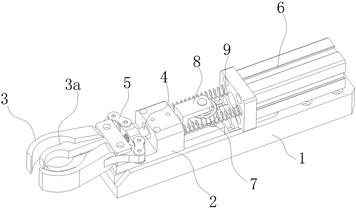
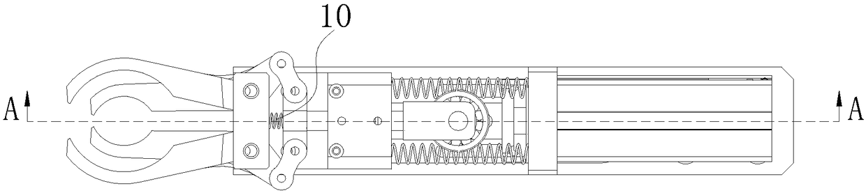
[0020] Such as Figure 1 to Figure 4 As shown, a hydraulic gripper for bottle caps includes a support plate 1, a moving block 2 that slides with the support plate 1, a symmetrically distributed jaw 3 that is hinged on the moving block 2, and a sliding fit with the moving block 2. The guide rod 4, one end is hinged on the guide rod 4 and the connecting plate 5 whose other end is hinged on the jaw 3, the hydraulic cylinder 6 that pushes the guide rod 4 to move during the elongation process, one end is connected to the moving block 2 and the other One end is connected to the spring 7 on the hydraulic cylinder 6.

[0021] The clamping jaws 3 are in an arc-shaped structure bent close to each other, and the clamping jaws 3 are connected with a tightening plate 3 a in the same bending directi...


PUM


Abstract

The invention relates to a hydraulic clamping hand for a bottle cap. The hydraulic clamping hand for the bottle cap comprises a supporting plate, a movable block, clamping jaws, a guiding rod, connecting plates, a hydraulic cylinder and springs, wherein the movable block is matched with the supporting plate in a sliding mode; the clamping jaws are distributed symmetrically and hinged to the movable block; the guiding rod is matched with the movable block in a sliding mode; one end of each of the connecting plates is hinged to the guiding rod, and the other end of each of the connecting platesis hinged to each of the clamping jaws; the hydraulic cylinder is used for pushing the guiding rod to move in the extending process; one end of each of the springs is connected to the movable block, and the other end of each of the springs is connected to the hydraulic cylinder. The clamping jaws are of curved arc-shaped structures which close to each other, and clamping plates with the same curving direction as the clamping jaws are connected to the clamping jaws. According to the hydraulic clamping hand for the bottle cap, structural design is reasonable, operation is simple, using is convenient, the effective contact surface between the clamping hand and the bottle cap is increased, the stability and assembling precision during clamping of the bottle cap are greatly improved, the lengthof the clamping hand is greatly prolonged, the installation of the bottle cap and a wine bottle is facilitated, and the cap pressing of the bottle is facilitated.

Description

technical field [0001] The invention relates to the technical field of wine processing equipment, in particular to a hydraulic gripper for bottle caps. Background technique [0002] The chemical composition of wine is ethanol, which generally contains traces of fusel alcohols and esters. Wine is made from grain through fermentation. As early as 2000 years ago, my country invented wine-making technology, and continuously improved and perfected it. Now it has developed to be able to produce various concentrations, various flavors, and various alcoholic beverages. [0003] The wine bottle needs to be capped after filling. Because the bottle cap has a hierarchical structure with different diameters on the upper and lower sides, the effective contact surface of the gripper is greatly reduced when the gripper touches the cap. Traditional grippers usually use non-slip friction pads. , to clamp the bottle cap, but still cannot increase the effective contact surface, so that the st...

Claims


Application Information

Patent Timeline
Patent Type & Authority Applications(China)
IPC IPC(8): B67B3/02
CPCB67B3/02
Inventor 陈启岳
Owner WUHU HUIYING AUTOMATIC EQUIP CO LTD
Why Eureka
Try Eureka