
Chirp laser pulse frequency spectrum shaping system based on angular spectral dispersion

A laser pulse and spectrum shaping technology, which is applied to lasers, laser components, semiconductor lasers, etc., can solve the problems of low pulse contrast or signal-to-noise ratio, low utilization rate of signal light energy, and low flexibility, so as to increase utilization efficiency, improve energy conversion efficiency, and increase the effect of spectral bandwidth

Pending Publication Date: 2018-07-13
CHENGDU NORMAL UNIV
View PDF5 Cites 8 Cited by
  • Summary
  • Abstract
  • Description
  • Claims
  • Application Information

AI Technical Summary

Problems solved by technology

Using this type of linear filtering technology, although the spectral width can be increased by one to two times, reaching a bandwidth of hundreds of nm, and the spectrum can be shaped, but usually the pulse contrast or signal-to-noise ratio coming out of the regenerative cavity is low; In addition, almost all these methods are in the form of clipping or clipping. At the cost of energy loss, the utilization rate of signal light energy is not high; finally, filter elements such as F-P etalons and birefringent filters generally only It is used to shape the optical spectrum of a signal. To obtain a spectrum distribution of any shape, it is necessary to redesign the device, which appears to be less flexible.

Method used


Image

  • Chirp laser pulse frequency spectrum shaping system based on angular spectral dispersion
  • Chirp laser pulse frequency spectrum shaping system based on angular spectral dispersion
  • Chirp laser pulse frequency spectrum shaping system based on angular spectral dispersion

Examples


Embodiment 1

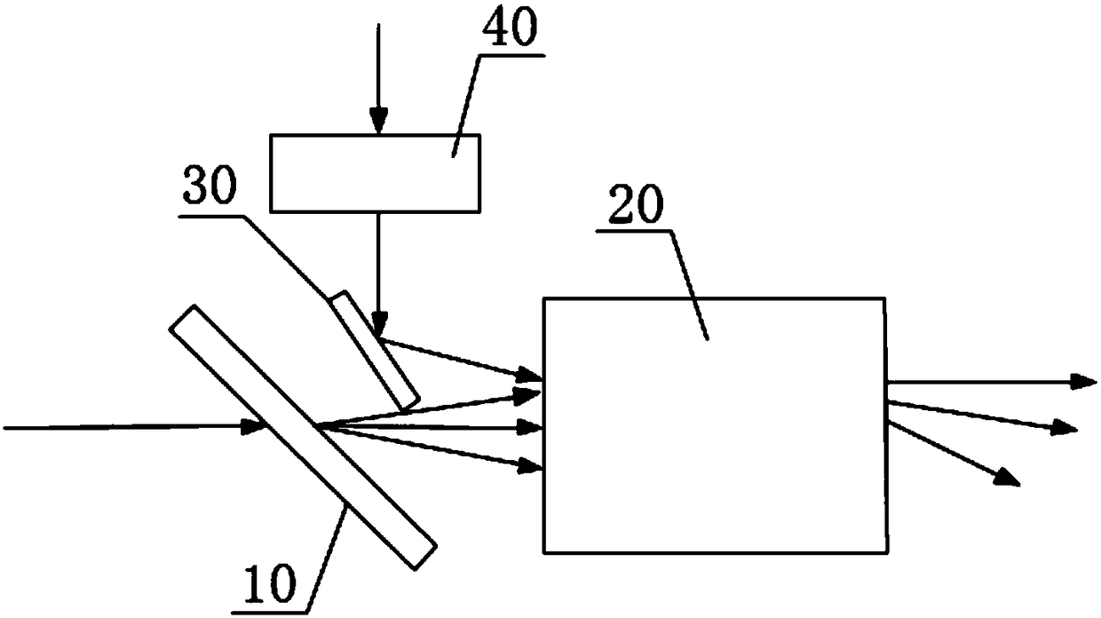
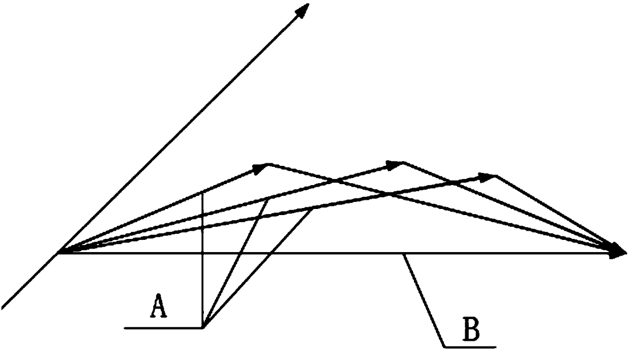
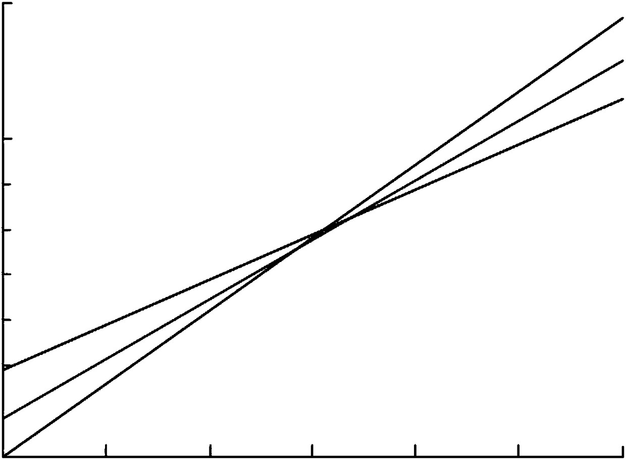
[0040] Such as Figure 1-5As shown, the chirped laser pulse spectrum shaping system based on spectral angular dispersion provided in this embodiment includes a dispersion module 10, an optical parameter conversion module 20, an optical delay module 40, and a reflection module 30; the dispersion module 10 is used to convert the chirped laser The light of different frequencies in the pulse is dispersed, the optical parametric conversion module 20 is used to parametrically couple the pump light incident on the crystal and the chirped laser pulse, and the optical delay module 40 is used to adjust the pump light pulse relative to the chirped laser pulse The time delay of the pulse reaching the optical parameter conversion module 20, the reflection module 30 is used to change the optical path direction of the pump light pulse; after the chirped laser pulse whose spectrum is to be shaped passes through the dispersion module 10, the light of different frequencies is dispersed by the di...


PUM


Abstract

The invention provides a chirp laser pulse frequency spectrum shaping system based on angular spectral dispersion, and relates to the technical field of laser pulse amplification. The chirp laser pulse frequency spectrum shaping system based on angular spectral dispersion comprises a chromatic dispersion module, an optical parameter conversion module, an optical delay module and a reflection module. After chirp laser pulse with frequency spectra to be shaped passes the chromatic dispersion module, light with different frequencies is dispersed by the chromatic dispersion module and then entersthe optical parameter conversion module by different incident angles, pump light pulse sequentially passes the optical delay module and the reflection module and then enters the optical parameter conversion module by incident angles non-collinear with the chirp laser pulse, the chirp laser pulse and the pump light pulse are subjected to energy transfer in the optical parameter conversion module and transmitted by the optical parameter conversion module to shape the frequency spectra of the chirp laser pulse, and the technical problems of low use rate of signal light energy, poor relative use flexibility and the like of a chirp laser pulse frequency spectrum shaping system in the prior art are relieved.

Description

technical field [0001] The invention relates to the technical field of laser pulse amplification, in particular to a chirped laser pulse spectrum shaping system based on spectral angular dispersion. Background technique [0002] Since the appearance of laser pulses, it has been developing in the direction of shorter and shorter pulse widths and higher and higher intensities. Ultra-short and ultra-intense laser pulses have extreme physical conditions such as strong electric field, strong magnetic field, and high pressure. Since D. Strcik and G. Mourou introduced the microwave-band chirped radar technology into the field of laser pulse amplification in 1985, and then formed the chirped pulse amplification technology, the development of high-power ultrashort laser pulses has begun a new journey. So far, many laboratories and research institutions in the world have adopted CPA technology as the main amplifier, and have successively obtained ultrashort pulse output with peak pow...

Claims


Application Information

Patent Timeline
Patent Type & Authority Applications(China)
IPC IPC(8): H01S3/00H01S5/00G02F1/03G02F1/21
CPCH01S3/0057H01S5/0057G02F1/0327G02F1/21
Inventor 叶荣吴显云谭航冯强朱鸿成
Owner CHENGDU NORMAL UNIV
Learn More