
Bearing seat with high tensile strength and bending strength

A bending-resistant and high-strength technology, applied in the direction of bearing components, shafts and bearings, and rigid supports of bearing components, can solve the problems of particularly serious loss of moving equipment, poor shock absorption effect of bearing seats, waste of materials and resources, etc. Simple structure, increase service life, reduce loss effect

Inactive Publication Date: 2018-07-13
响水县金固轴承座制造有限公司
View PDF0 Cites 5 Cited by
  • Summary
  • Abstract
  • Description
  • Claims
  • Application Information

AI Technical Summary

Problems solved by technology

[0002] The upper cover and the base of the split bearing seat can be separated, and mainly bear radial loads. It is suitable for spherical roller bearings and self-aligning ball bearings with cylindrical holes and tapered holes. In the industrial production process, the loss of moving equipment is particularly serious. Among them, the large proportion of faults is also the moving equipment. The main loss and failure of the moving equipment come from the force in different directions. The combination of forces in different directions will cause vibration. If the vibration of the equipment is too large, its service life will be shortened. It will be greatly reduced, which greatly wastes materials and resources. However, the most important part to reduce equipment vibration is the bearing seat. In the existing technology, the shock absorption effect of the bearing seat is poor, and it cannot be stretched and bent, and cannot meet The needs of today's industrial production

Method used


Image

  • Bearing seat with high tensile strength and bending strength
  • Bearing seat with high tensile strength and bending strength

Examples


Embodiment Construction

[0019] The technical solutions in the embodiments of the present invention will be clearly and completely described below with reference to the accompanying drawings in the embodiments of the present invention. Obviously, the described embodiments are only a part of the embodiments of the present invention, but not all of the embodiments.

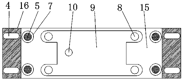
[0020] refer to Figure 1-2 , a bearing seat with high tensile and bending strength, including a base 16 and a seat cover 9, the top outer wall of the seat cover 9 is provided with an oil injection hole, and the inner wall of the oil injection hole is sleeved with an oil injection nozzle 10, and the top inner wall of the seat cover 9 A bearing groove 12 is provided, and the inner wall of the bearing groove 12 is sleeved with a rubber gasket 13, the outer walls of both sides of the seat cover 9 are welded with limit rings 11, and the four corners of the outer wall of the top end of the seat cover 9 are provided with joint screw holes 8, and t...


PUM


Abstract

The invention discloses a bearing seat with high tensile strength and bending strength. The bearing seat comprises a base and a seat cover. An oil injection hole is formed in the outer wall of the topend of the seat cover, an oil injection nozzle is sleeved with the inner wall of the oil injection hole, a bearing groove is formed in the inner wall of the top end of the seat cover, and a rubber washer is sleeved with the inner wall of the bearing groove. Limiting rings are welded to the outer walls of the two sides of the seat cover, joint screw holes are formed in the four corners of the outer wall of the top end of the seat cover and connected with a lower seat through bolts, and a second bearing groove is formed in the outer wall of the top end of the lower seat. Through the additionalarrangement of the rubber washer, bearings can have a buffer movement space; through the additional arrangement of guide posts and springs, the bearing seat can resist the displacement status generated during mechanical work; through the arrangement of the linear motion bearings, the losses of the guide posts are reduced; and the device is simple in structure, high in tensile strength and bendingstrength, obvious in effect and long in service life, and therefore the losses of enterprise equipment are greatly reduced.

Description

technical field [0001] The invention relates to the technical field of bearing seats, in particular to a bearing seat with high tensile and bending strength. Background technique [0002] The upper cover and the base of the split bearing housing can be separated, and mainly bear radial load. It is suitable for spherical roller bearings and spherical ball bearings with cylindrical holes and tapered holes. In the process of industrial production, the loss of moving equipment is particularly serious. , Among them, the proportion of failures is also the moving equipment. The main loss and failure of the moving equipment come from the force in different directions. The force in different directions will cause vibration. If the vibration of the equipment is too large, its service life will be shortened. It will be greatly reduced, and the materials and resources will be greatly wasted. However, the most important accessory to reduce equipment vibration is the bearing seat. In the ...

Claims


Application Information

Patent Timeline
Patent Type & Authority Applications(China)
IPC IPC(8): F16C35/04F16F15/08
CPCF16C35/04F16F15/08
Inventor 沈继祥
Owner 响水县金固轴承座制造有限公司
Learn More