Automatic processing technology of vvt valve sleeve

A processing technology and valve sleeve technology, which is applied in the field of VVT valve sleeve automatic processing technology, can solve the problems of high cost and low efficiency, and achieve the effects of high tool life, high service life, and high processing dimensional accuracy

Active Publication Date: 2019-10-25
四川融至精密机械有限公司
View PDF10 Cites 0 Cited by
  • Summary
  • Abstract
  • Description
  • Claims
  • Application Information

AI Technical Summary

Problems solved by technology

[0004] The purpose of the present invention is to provide an automatic processing technology for VVT valve sleeves to solve the problems of low efficiency and high cost caused by the existing automatic processing technology

Method used


Image

  • Automatic processing technology of vvt valve sleeve
  • Automatic processing technology of vvt valve sleeve
  • Automatic processing technology of vvt valve sleeve

Examples


Embodiment 1

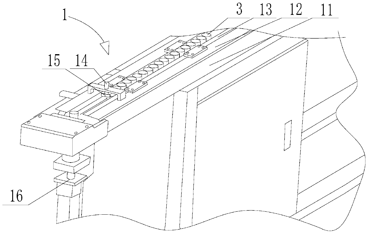
[0054] Such as Figure 1 to Figure 3 As shown, the automatic processing technology of VVT valve sleeve includes the following steps:

[0055] 1), the feeding device 1 transports the VVT ​​valve sleeve 3 to the grip position of the robot;

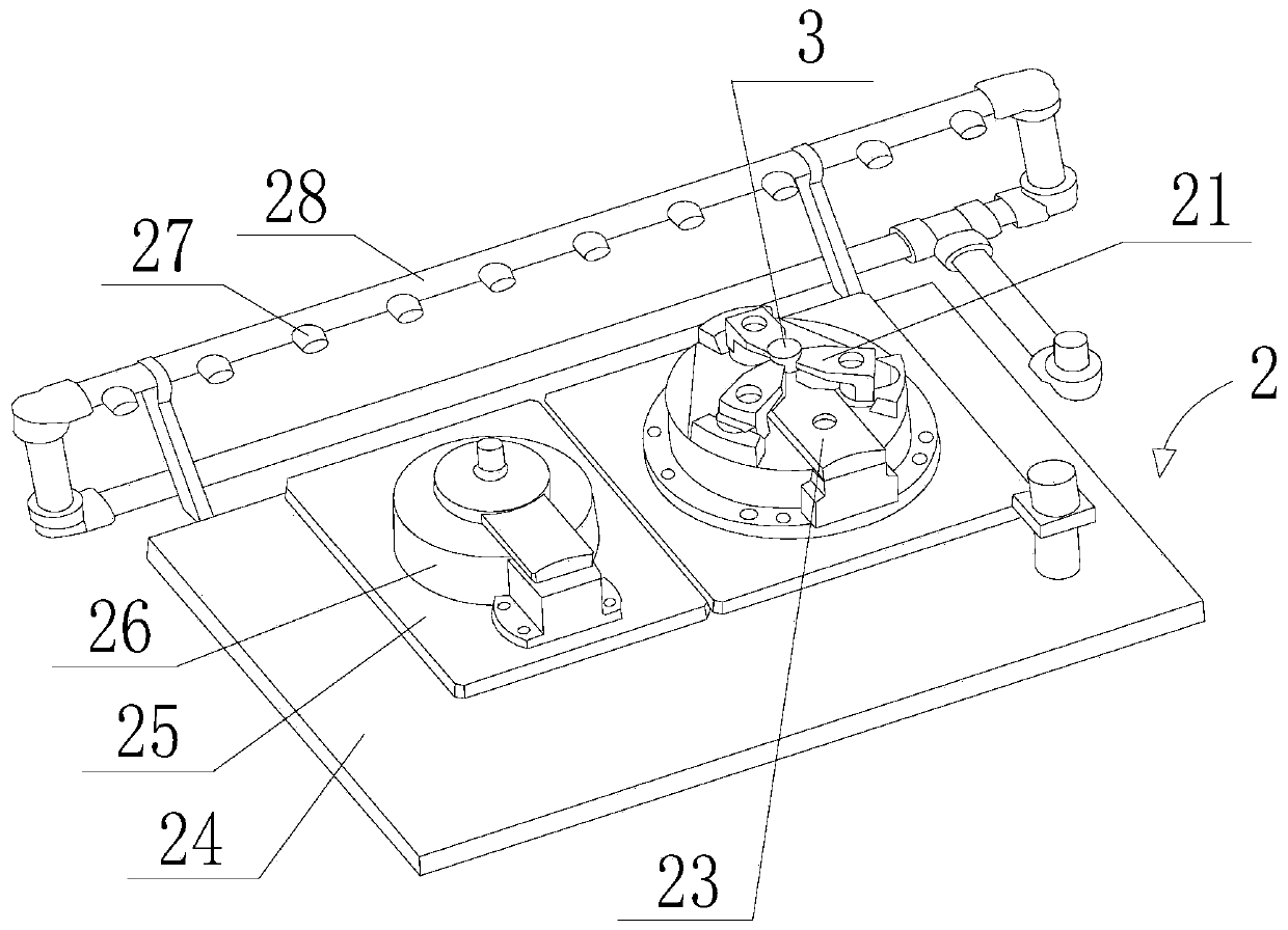
[0056] 2), the robot grabs the positioning surface 23 of the VVT ​​valve sleeve 3 close to the fixture 2 and prepares for clamping;

[0057] 3), the positioning surface 23 and the VVT ​​valve sleeve 3 of the clamp 2 are blown to clean the clamp 2, specifically, through the automatic control technology, the injection port 27 is automatically sprayed, and the gas is injected to the processing surface of the positioning surface 23 and the VVT ​​valve sleeve 3 ( upper end surface) to clean the positioning surface 23 and the VVT ​​valve sleeve 3, so as to avoid impurities such as iron filings and dust affecting the positioning accuracy of the parts;

[0058] 4), the robot installs the VVT ​​valve sleeve 3 on the positioning surface 23 of the fi...

Embodiment 2

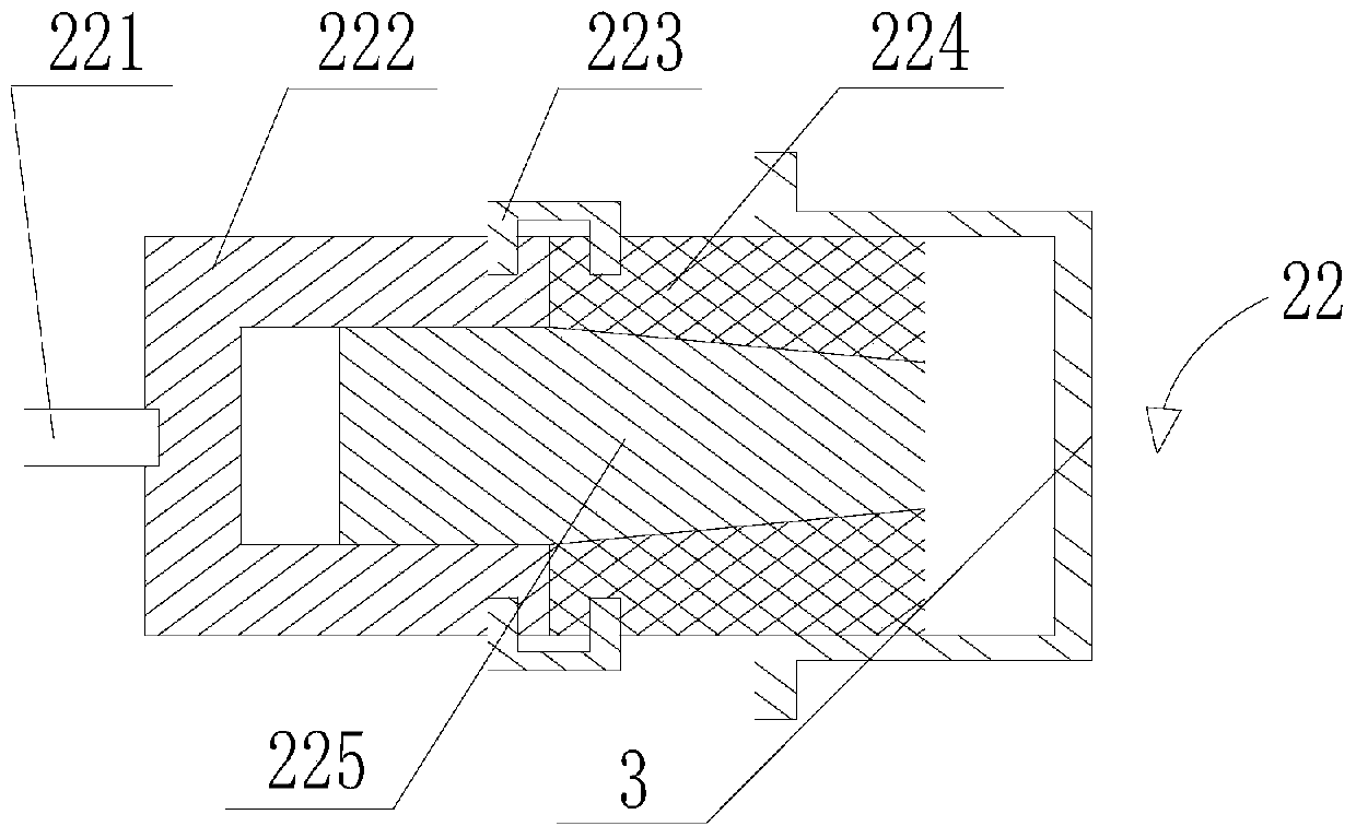
[0075] Such as Figure 1 to Figure 3 As shown, this embodiment is based on Embodiment 1. The fixing groove 222 and the inner expansion sleeve 224 are connected by a connecting piece 223. The section of the connecting piece 223 in the axial direction is a U-shaped structure, and the U-shaped structure One side is inserted into the fixing groove 222 , and the other side is inserted into the inner expansion sleeve 224 .

[0076] In this embodiment, through the arrangement of the connecting piece 223 , the detachable arrangement between the inner expansion sleeve 224 and the fixing groove 222 is realized, which facilitates the replacement of the inner expansion sleeve 224 .

[0077] Example 2:

[0078] Such as Figure 1 to Figure 3 As shown, the present embodiment is based on Embodiment 1 or Embodiment 2. The machining center also includes an automatic measuring machine, which is configured in the production line, and adopts internationally renowned sensors such as Keyence and I...


PUM


Abstract

The invention discloses a VVT valve sleeve automatic machining technology. The VVT valve sleeve automatic machining technology comprises the following steps that (1), a VVT valve sleeve is transportedto a robot hand-grabbing position by a feeding device; (2), the robot grabs the positioning surface, close to a clamp, of the VVT sleeve to prepare for clamping; (3), the clamp blows to clean the positioning surface and the VVT valve sleeve; (4), the VVT valve sleeve is installed on the positioning surface of the clamp by the robot; (5), the VVT valve sleeve is pressed by grippers of the robot, and the VVT sleeve is fixed on the positioning surface by a clamping mechanism on the clamp; (6), whether the VVT valve sleeve is installed in place or not is detected by the clamp through gas detection; and (7), after confirming that the VVT valve sleeve is installed in place, the VVT valve sleeve is subjected to tool machining by a tool, and the tool is mounted on a machine tool. All steps are completed centrally in a machining center. The clamp comprises a front face machining station and a back face machining station, the clamp further comprises an air blowing device, and the air blowing device comprises a pipeline and a jet opening formed in the pipeline. The VVT valve sleeve automatic machining technology solves the problems of low efficiency and high cost caused by an existing automatic machining technology.

Description

technical field [0001] The invention relates to the technical field of VVT valve sleeve processing, in particular to an automatic processing technology of a VVT valve sleeve. Background technique [0002] Today, with the rapid development of automated processing technology, the processing of most mechanical parts is gradually transforming, but some precision parts have low processing efficiency and low quality level due to traditional processing technology, resulting in high automation input costs and high operating costs. The automated production line was unable to operate, and production was discontinued. [0003] The traditional processing of VVT valve sleeve adopts CNC lathe and some processing centers to form an assembly line for processing. It needs to complete most of the processes such as turning the outer circle, drilling, boring the inner hole, grooving, chamfering, etc. If the traditional process is used to realize automation, the processing efficiency is low. Th...

Claims


Application Information

Patent Timeline
Patent Type & Authority Patents(China)
IPC IPC(8): B23P15/00B23Q3/06B23Q7/00B23Q7/04B23Q11/00B23Q11/12B23Q17/00B23Q17/20B23B19/02
CPCB23P15/001B23Q1/70B23Q3/062B23Q7/00B23Q7/04B23Q11/0046B23Q11/005B23Q11/127B23Q17/002B23Q17/20
Inventor 林德亮黄榆鉴
Owner 四川融至精密机械有限公司
Why Eureka
Try Eureka