
Electric lifting technology based punching device for construction

A drilling device and construction technology, applied in the direction of positioning device, boring/drilling, drilling/drilling equipment, etc., can solve the problems of high risk, inconvenient use, easy to be injured, etc., to ensure stability High performance, flexible position control, and the effect of improving drilling quality

Inactive Publication Date: 2018-07-13
上海华普钢结构股份有限公司
View PDF7 Cites 4 Cited by
  • Summary
  • Abstract
  • Description
  • Claims
  • Application Information

AI Technical Summary

Problems solved by technology

When the existing punching device is in use, in order to stably punch the object, the object is generally clamped by tightening the bolt. Although the hole can be stably punched, it is time-consuming and laborious to tighten the bolt, which makes it inconvenient to use, and the punching After the punching machine is finished, it is inconvenient to separate from the object, which once again causes the punching machine to be difficult to use; and the existing punching machine usually requires a hand-held punching machine to complete the work for the ground fixing device, but, This kind of hand-held punching machine is only suitable for drilling small holes. For some large holes, it cannot be completed, and the hand-held punching machine usually needs manual assistance to complete, which is relatively dangerous and prone to In the case of injury, it is very inconvenient to use

Method used


Image

  • Electric lifting technology based punching device for construction
  • Electric lifting technology based punching device for construction
  • Electric lifting technology based punching device for construction

Examples


Embodiment Construction

[0021] It should be noted that, in the case of no conflict, the embodiments of the present invention and the features in the embodiments can be combined with each other.

[0022] In describing the present invention, it should be understood that the terms "center", "longitudinal", "transverse", "upper", "lower", "front", "rear", "left", "right", " The orientations or positional relationships indicated by "vertical", "horizontal", "top", "bottom", "inner" and "outer" are based on the orientations or positional relationships shown in the drawings, and are only for the convenience of describing the present invention and Simplified descriptions, rather than indicating or implying that the device or element referred to must have a particular orientation, be constructed and operate in a particular orientation, and thus should not be construed as limiting the invention. In addition, the terms "first", "second", etc. are used for descriptive purposes only, and should not be understood ...


PUM


Abstract

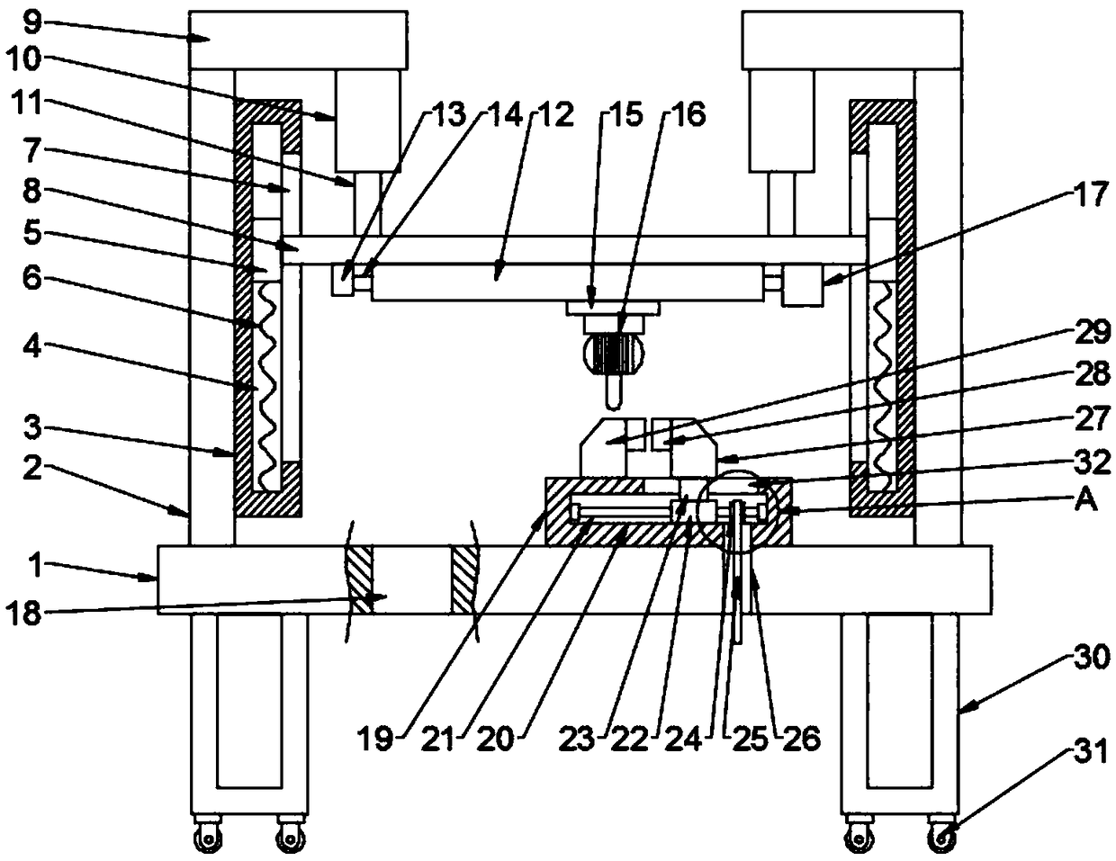
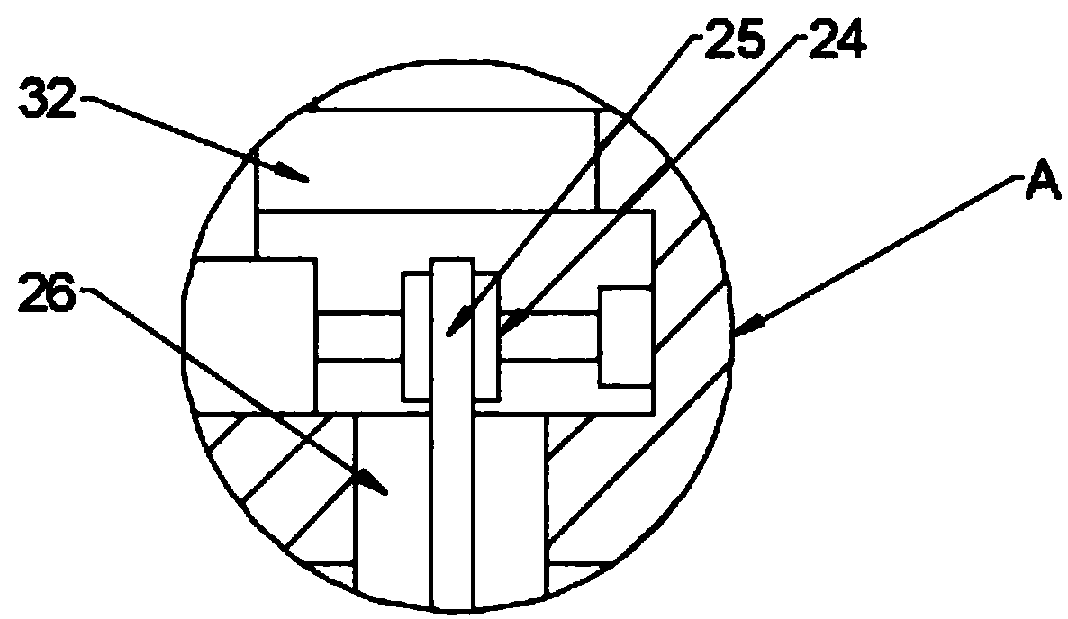
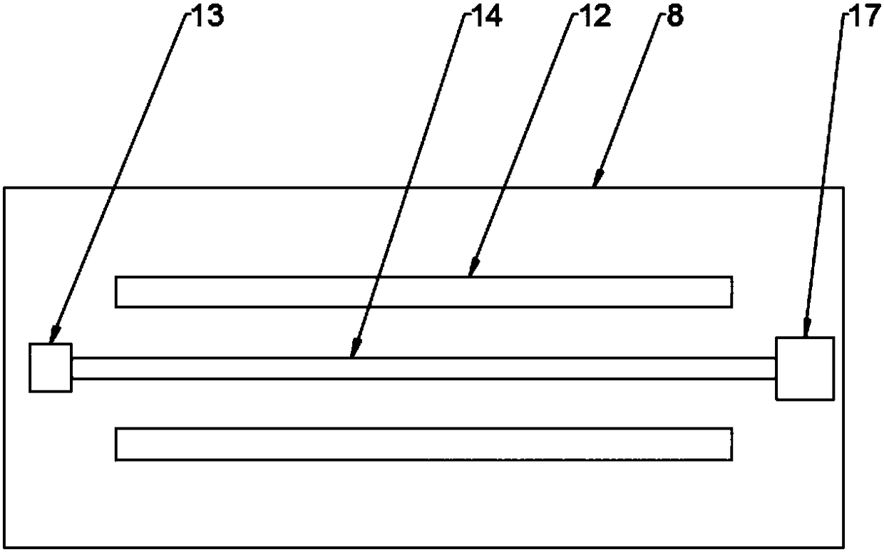
The invention discloses an electric lifting technology based punching device for construction. The electric lifting technology based punching device comprises a bottom plate; a seat box and two upright columns are arranged on the top end face of the bottom plate; lifting barrels are arranged at the adjacent ends of the upright columns; lifting groove holes are formed in the lifting barrels; sliding holes are formed in one side ends, far from the upright columns, of the lifting groove holes; sliding blocks are arranged in the lifting groove holes; a transverse plate fitting with the sliding holes is fixedly connected between the two sliding blocks; guide rails are arranged at the bottom end face of the transverse plate in a front and rear symmetrical manner; a lead screw is arranged betweenthe two guide rails; the lead screw is sleeved with a movable seat fitting with the guide rails; and the movable seat is fixedly connected with a drilling machine. Through mutual fitting between adopted electric telescopic rods and the transverse plate, the drilling machine can achieve multi-directional movement in a space, position control is flexible, and a ground fixing device and a movable object are dilled conveniently; and through mutual fitting between a fixed clamp and a movable clamp, a to-be-drilled object can be fixedly and effectively clamped, the stability of the to-be-drilled object is ensured, and the drilling quality is improved.

Description

technical field [0001] The invention relates to the technical field of building drilling equipment, in particular to a building drilling device based on electric lifting technology. Background technique [0002] Construction engineering refers to the engineering entity formed through the construction of various housing buildings and their ancillary facilities and the installation activities of supporting lines, pipelines and equipment. Among them, "housing construction" refers to projects that have roofs, beams, walls, foundations, and can form internal spaces to meet people's needs for production, living, learning, and public activities. [0003] Construction engineering refers to the planning, survey, design and construction, completion and other technical work and the completed engineering entity and the installation project of the supporting lines, pipelines and equipment for new construction, reconstruction or expansion of houses, buildings and auxiliary structures and ...

Claims


Application Information

Patent Timeline
Patent Type & Authority Applications(China)
IPC IPC(8): B23B39/14B23Q3/06
Inventor 朱园园
Owner 上海华普钢结构股份有限公司
Learn More