Liquid material heat-preservation device and application thereof

A technology of heat preservation device and material, applied in the field of material heat preservation, can solve the problems of high cost of automatic control system, unclean cleaning, insufficient speed, etc., and achieve simple control instrument and automatic control system, continuously adjustable heat preservation time, and high energy recovery rate. Effect

Pending Publication Date: 2018-07-13
沐清洲
View PDF0 Cites 0 Cited by
  • Summary
  • Abstract
  • Description
  • Claims
  • Application Information

AI Technical Summary

Problems solved by technology

However, since the flow rate of the material entering the pipeline is constant, when the material suddenly enters a pipeline with a large diameter, the flow rate of the material in the pipeline is very low.
Once the flow rate is very low, a "first in, first out" plug flow cannot occur in this large pipeline, so it is impossible to ensure that all materials have the same heat preservation time in this heat preservation section
Second, for some materials that need to be cleaned in place (Clean In Place) or are prone to fouling, if the flow rate is too low, the cleaning will not be clean or due to the low flow rate, the speed of the material fluid flowing through the inner surface of the pipeline will not be sufficient, resulting in precipitation (scaling)
[0011] 2) The cost of the three insulation tanks is high: in addition to the tank itself, many valves need to be configured for switching between tanks, each tank needs corresponding control instruments, and complex material inlet and outlet pipes need to be configured In addition, the cost of the corresponding automatic control system is relatively high;
[0012] 3) The three tanks are arranged in parallel, including the reserved maintenance space, and the total floor area is relatively large, resulting in an increase in land cost and construction cost;
[0013] 4) If other additional functions are considered, such as evaporation condensation / vacuum degassing during heat preservation, etc., the gas pipeline will be complicated, the pressure loss will be large, the vacuum energy consumption will be high, and the cost will be high;
[0014] 5) If the solution of the three heat preservation tanks is further improved: the current fixed heat preservation time is improved to continuously stepless adjustable heat preservation time, the cost of the control instruments and automatic control of the three heat preservation tanks will be higher

Method used


Image

  • Liquid material heat-preservation device and application thereof
  • Liquid material heat-preservation device and application thereof
  • Liquid material heat-preservation device and application thereof

Examples


Embodiment 1

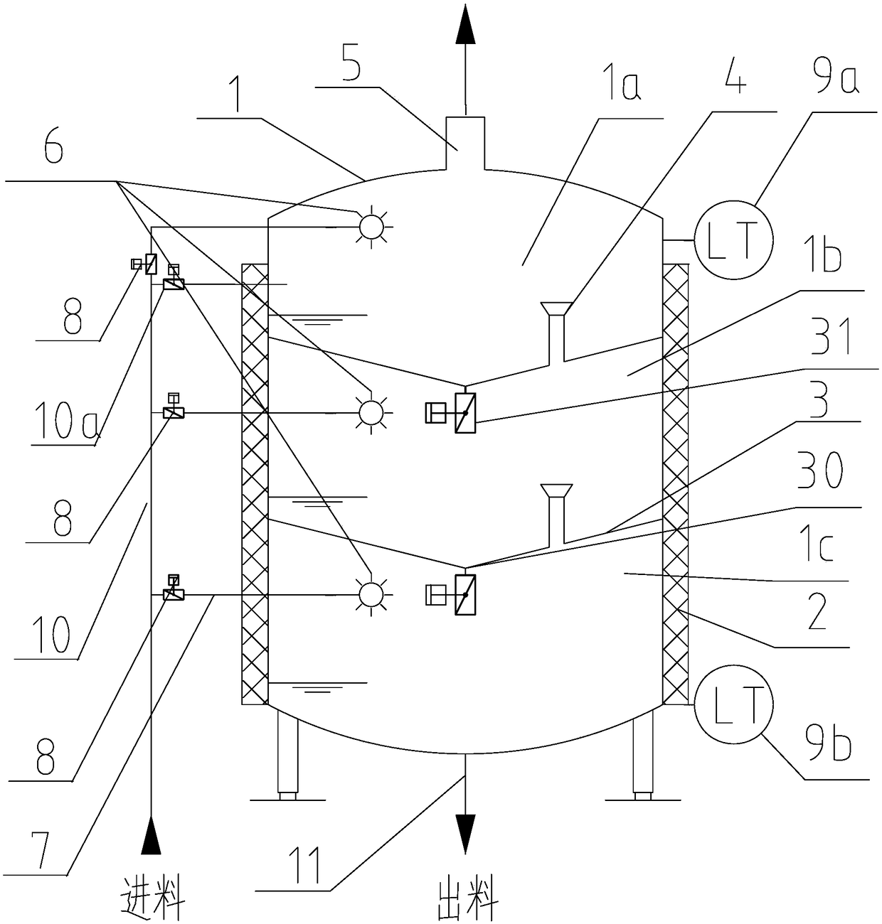
[0076] Such as figure 1Shown, a kind of liquid material insulation device, this insulation device includes insulation tower, control system (not shown in the figure), instruments such as flow meter etc. (not shown in the figure, can be set according to the conventional means of this field). The heat preservation tower includes a tower body 1 arranged upright, an insulation layer 2 arranged on the outer periphery of the tower body 1, and two partitions 3 horizontally arranged in the tower body 1. The two partitions 3 separate the tower body 1 into upper, middle and The lower three interlayers (hereinafter respectively referred to as feed layer 1a, insulation layer 1b and discharge layer 1c), feed layer 1a and discharge layer 1c are respectively provided with liquid level sensors 9a, 9b, feed layer 1a and feed layer The pipe 10 is connected, and the discharge layer 1c is connected with the discharge pipe 11. The feed pipe 10 and the discharge pipe 11 are respectively provided wi...

Embodiment 2

[0088] Such as Figure 6 As shown, this embodiment provides a liquid material heat preservation device, which is basically the same as Embodiment 1, the difference is that there are 4 partitions in this example, so that the inner space of the tower body 1 is divided into 5 partitions.

[0089] The method of adopting this embodiment to carry out material insulation is the same as that of Embodiment 1, except that the setting value and residence time of the control materials in each compartment are different. Specifically, the flow rate of the liquid material to be insulated is 30m 3 / h, the holding time is 30 minutes as an example, the material setting value of the control switch valve is 30m 3 / h* 0.5h / 3=5m 3 . The material residence time in each insulation layer is 10min. From the beginning of feeding to the subsequent stable cycle, the total time required is 50 minutes. During the entire continuous heat preservation process, there is a total of 80 minutes of heat energy ...

Embodiment 3

[0091] This embodiment provides a liquid material heat preservation device, which is basically the same as Embodiment 2, except that there are 5 partitions in this example, so that the inner space of the tower body is divided into 6 partitions.

[0092] The flow rate of the liquid material to be insulated is 30m 3 / h, the holding time is 30 minutes as an example, the material setting value of the control switch valve is 30m 3 / h*0.5h / 4=3.75m 3 . The residence time of materials in each insulation layer is 7.5 minutes. From the beginning of feeding to the subsequent stable cycle, the total time required is 45 minutes. During the entire continuous heat preservation process, there is a total of 75 minutes of heat energy that has not been recovered. Correspondingly, the volume of each compartment can be set to 3.75m 3 Or slightly more than 3.75m 3 , the total volume of the tower can be about 22m 3 . Compared with Example 1, the volume of the tower body can be reduced by 50% ...


PUM


Abstract

The invention relates to a liquid material heat-preservation device and application thereof. The liquid material heat-preservation device comprises a heat-preservation tower, a feeding pipe, a cleaning device and a discharging pipe, wherein the heat-preservation tower comprises a tower body; the tower body has at least a plurality of interlayers arranged in a vertical direction, wherein an uppermost interlayer is communicated with the feeding pipe; a lowermost interlayer is communicated with the discharging pipe; the two adjacent interlayers are communicated; and switching valves are arrangedat communicated parts. The liquid material heat-preservation device provided by the invention is suitable for heat preservation of all liquid materials, can be used for pure heat-preservation, can also be used for heat preservation for specific purposes such as realizing sterilization or achieving certain biological or chemical reactions like Maillard reaction, and is used for liquid materials, particularly liquid foods and medicines (including but not limited to raw medicinal materials). The liquid material heat-preservation device is particularly suitable for heat preservation when a flow rate of the liquid materials is high and / or the required heat preservation time is long, and has the advantages of small occupied area, reliable operation, low investment cost, good energy saving effectand various uses.

Description

technical field [0001] The invention relates to material heat preservation technology, in particular to a liquid material heat preservation device and heat preservation method. The heat preservation device of the present invention is especially suitable for large flow and / or long heat preservation time, and it needs to be sterilized by heating (including pasteurization and ultra-high temperature sterilization Ultra Heat Treatment) to obtain biologically stable liquid Material, or liquid material that needs to be heated at high temperature for a long time to promote the reaction of the material (including but not limited to Maillard reaction, etc.). The liquid material includes but not limited to food, medicine (including raw material medicine) and the like. Background technique [0002] For safety reasons, food and medicine (including raw materials) generally need to be sterilized during the production process to improve their biological stability. In addition, for some p...

Claims


Application Information

Patent Timeline
Patent Type & Authority Applications(China)
IPC IPC(8): B01D19/00B01D53/00B01J19/00A23L5/20
CPCB01D19/00B01D53/002B01J19/0013A23L5/20A23L5/21B01J2219/00155Y02P60/85
Inventor 沐清洲
Owner 沐清洲
Why Eureka
Try Eureka