Tooth-socket bilateral primary permanent magnet synchronous linear motor
A technology of synchronous linear motors and permanent magnets, applied in the direction of electrical components, electromechanical devices, electric components, etc., can solve the problems of low pitch factor of phase windings, influence of motor efficiency, and excessive length of winding ends, so as to improve output power and Efficiency, improve power factor, improve the effect of sinusoidal degree
- Summary
- Abstract
- Description
- Claims
- Application Information
AI Technical Summary
Problems solved by technology
Method used
Image
Examples
Embodiment 1
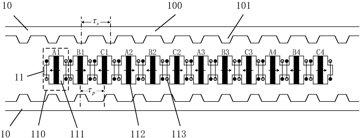
[0061] see figure 1 , the cogging type bilateral primary permanent magnet synchronous linear motor of the present invention adopts the first type of winding,
[0062]
[0063] In this embodiment, m=3, t=0, k=1, n=4, and the sign is positive, so the pole distance ratio τ p / τ s Set at 5 / 6, which is 10 / 12. Wherein, m is the phase number of the motor, k is the logarithm of the same-phase armature winding 113 in each motor unit, and n is the number of motor units.
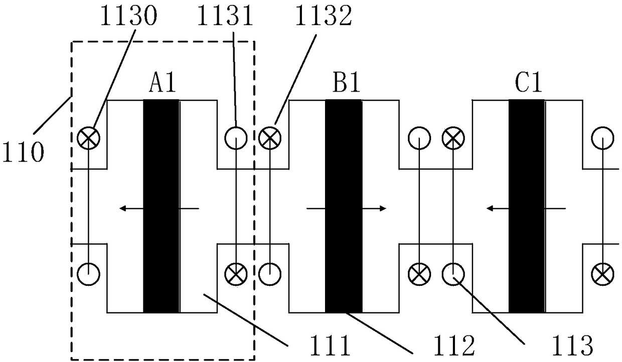
[0064] The cogging type bilateral primary permanent magnet synchronous linear motor of the present invention comprises two unilateral secondary 10, primary 11 and armature winding 113, and unilateral secondary 10 and primary 11 are all salient pole structures, and above-mentioned secondary 10 and primary 11 There is an air gap between them. In this embodiment, m=3, that is, the motor in this embodiment is a three-phase motor consisting of three phases A, B, and C. Primary 11 comprises k*m*n=12 basic units 110 ....
Embodiment 2
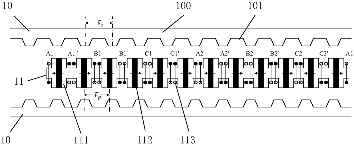
[0070] image 3 It is also a cogging type bilateral primary permanent magnet synchronous linear motor. The difference between this embodiment and Embodiment 2 is that this embodiment adopts the second type of winding, and the pole pitch ratio satisfies
[0071]
[0072] In this embodiment, m=3, k=4, t=0, n=1, the sign is negative, and the pole distance ratio τ p / τ s =11 / 12.
[0073] In this embodiment, the armature windings 113 in the same primary slot 11 have the same winding direction, and the armature windings 113 in k / 2=2 consecutive primary slots are in-phase windings, wherein the armature windings between adjacent slots The winding direction of 113 is opposite; and the winding direction of adjacent phase windings is opposite; m*k=12 continuous basic units 110 constitute a motor unit;
[0074] The advantages of this example are similar to those of Example 1: the bilateral normal suction forces cancel each other out, reducing the friction loss of the system; it is ...
Embodiment 3
[0076] image 3 It is also a cogging type bilateral primary permanent magnet synchronous linear motor. The difference between this embodiment and Embodiment 1 is that this embodiment adopts the third type of winding, and the pole pitch ratio satisfies
[0077]
[0078] In this embodiment, m=3, k=4, t=0, n=1, the positive and negative signs are positive, and the pole distance ratio τ p / τ s =14 / 24, namely τ p / τ s =7 / 12.
[0079] In this embodiment, the armature windings 113 in the same primary slot 11 have the same winding direction, and the armature windings 113 in k / 2=2 consecutive primary slots are in-phase windings, wherein the armature windings between adjacent slots The winding direction of 113 is the same, m*k=12 continuous basic units 110 constitute a motor unit;
[0080] In this example, on the basis of balanced normal force, simple structure and easy maintenance, the pitch factor of the coil is improved, while the length of the coil end does not change, and ...
PUM
 Abstract
Description
Claims
Application Information
 - R&D
- Intellectual Property
- Life Sciences
- Materials
- Tech Scout
- Unparalleled Data Quality
- Higher Quality Content
- 60% Fewer Hallucinations
Browse by: Latest US Patents, China's latest patents, Technical Efficacy Thesaurus, Application Domain, Technology Topic, Popular Technical Reports.
© 2025 PatSnap. All rights reserved.Legal|Privacy policy|Modern Slavery Act Transparency Statement|Sitemap|About US| Contact US: help@patsnap.com


