
Bifurcated covered stent

A covered stent and bifurcation technology, applied in the field of medical devices, can solve problems such as unfavorable blood flow passage, impact, and poor interface shape

Pending Publication Date: 2018-07-10
LIFETECH SCIENTIFIC (SHENZHEN) CO LTD
View PDF9 Cites 4 Cited by
  • Summary
  • Abstract
  • Description
  • Claims
  • Application Information

AI Technical Summary

Problems solved by technology

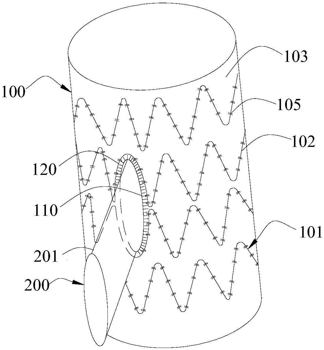
In the two ways, the former main body and the side branch metal bracket are integrated to ensure the interface shape of the side branch, but the integrated metal bracket structure limits the flexibility between the side branch and the main body, and the latter main body and the side branch bracket are separated. Independent metal stent structure, although there is good flexibility between the side branch and the main body, but the position of the side branch interface is not supported by the metal stent, and the interface shape is not good, which will affect the establishment of the follow-up surgical guide wire through the main body stent Orbital process, and is also not conducive to the passage of blood flow

Method used


Image

  • Bifurcated covered stent
  • Bifurcated covered stent
  • Bifurcated covered stent

Examples


Embodiment Construction

[0030] In order to make the above objects, features and advantages of the present invention more comprehensible, specific implementations of the present invention will be described in detail below in conjunction with the accompanying drawings. In the following description, numerous specific details are set forth in order to provide a thorough understanding of the present invention. However, the present invention can be implemented in many other ways different from those described here, and those skilled in the art can make similar improvements without departing from the connotation of the present invention, so the present invention is not limited by the specific implementations disclosed below.

[0031] It should be noted that when an element is referred to as being “fixed on” or “disposed on” another element, it may be directly on the other element or there may be an intervening element. When an element is referred to as being "connected to" another element, it can be directl...


PUM


Abstract

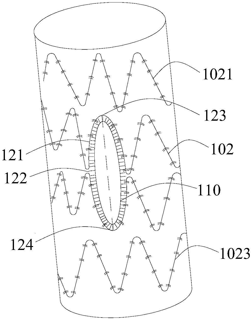
The invention discloses a bifurcated covered stent, which comprises a tubular main body and a lateral branch which communicates with the tubular main body, wherein the tubular main body comprises a first bare stent and a first membrane which is arranged on the bare stent; the first bare stent comprises at least one non-end wave-shaped ring; the lateral branch comprises a second membrane; the second membrane is connected to the first membrane; an expansion ring, which is distributed along the periphery of an interface of the first membrane and the second membrane, is arranged on the interface;and the expansion ring is at least partially arranged on the circumferential surface, which is provided with the non-end wave-shaped ring, of the tubular main body. According to the bifurcated coveredstent, since the expansion ring is arranged on the interface and the expansion ring is at least partially arranged on the circumferential surface, which is provided with the non-end wave-shaped ring,of the tubular main body, the expansion ring can achieve radial expansion along with the self-expansion of the first bare stent after the release of the stent, so that a radial width on the interfacecan be kept, and subsequently, blood can smoothly flow into the lateral branch from the interior of the tubular main body via the interface; therefore, a smooth and sufficient blood flow is guaranteed in the lateral branch; and a guide wire can enter the lateral branch easily.

Description

technical field [0001] The invention relates to the technical field of medical devices, in particular to a bifurcated covered stent graft. Background technique [0002] Aneurysm is a clinically common vascular disease, which mostly occurs in the elderly. This disease can easily lead to aortic aneurysm rupture, which poses a great threat to the life of patients. General surgery was once considered the only way to treat aortic aneurysm. The only way, but this method is extremely dangerous. [0003] With the continuous development of medical technology, the use of minimally invasive surgery to implant covered stents into the human body to treat aortic aneurysms and dissecting aneurysms is being used more and more. This treatment method compresses the artificial covered stent into the delivery device, guides it into the human body along the previously implanted guide wire, releases the covered stent to the lesion, isolates the aneurysm cavity and forms a new blood flow channel,...

Claims


Application Information

Patent Timeline
IPC IPC(8): A61F2/07
CPCA61F2/07
Inventor 汪泽辉刘彩萍肖本好
Owner LIFETECH SCIENTIFIC (SHENZHEN) CO LTD
Learn More