Detection method, device and system for control channel
A control channel and detection method technology, applied in the field of communication, can solve the problem of low robustness, and achieve the effects of improving robustness, optimizing the process of control channel detection, and improving user experience.
- Summary
- Abstract
- Description
- Claims
- Application Information
AI Technical Summary
Problems solved by technology
Method used
Image


Examples
Embodiment 1
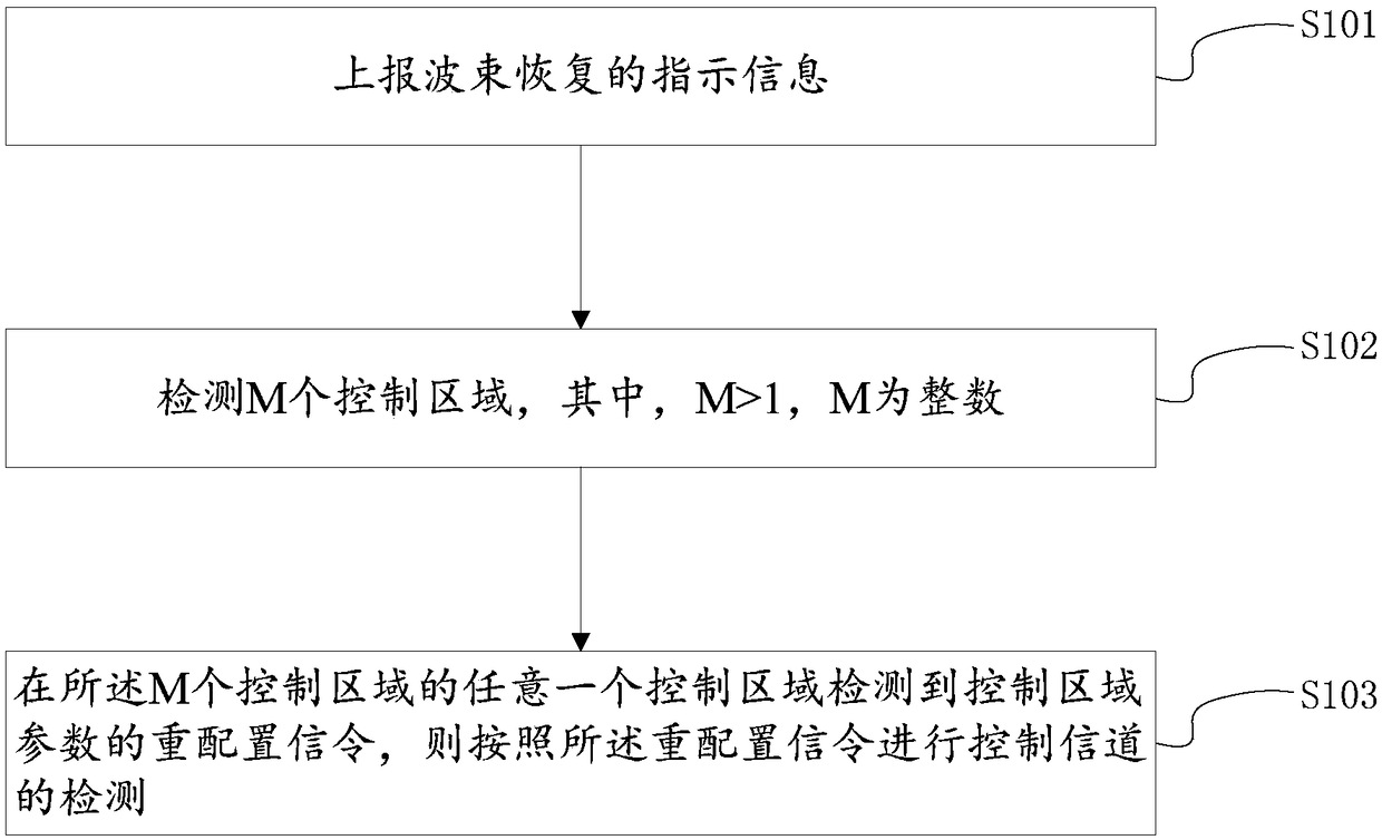
[0090] figure 2 This is a schematic flow chart of a control channel detection method provided in the first embodiment of the present disclosure, such as figure 2 As shown, the first embodiment provides a control channel detection method, which is applied to a transmitting end (terminal), and the method includes:
[0091] Step S101: Report the indication information of beam recovery.
[0092] Specifically, the transmitting end (terminal) monitors the beam. The monitoring process is mainly to judge the beam failure (beam failure) based on the reference signal. If beam recovery is required, the transmitting end (terminal) will report for beam recovery For example, the instruction information may be the instruction information of the transmitting end (terminal), beam instruction information, etc.
[0093] Step S102: After reporting the indication information, detect M control areas, where M> 1, M is an integer.
[0094] Specifically, after reporting the indication information, the sendi...
Embodiment 2
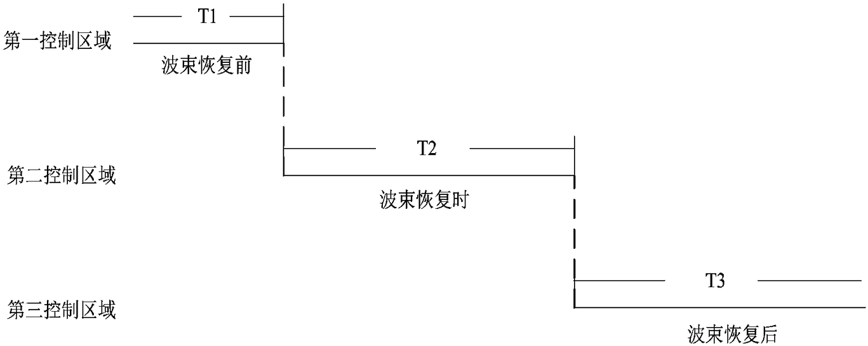
[0107] image 3 This is a schematic diagram of a control channel detection method provided in the second embodiment of this disclosure, such as image 3 As shown, in the second embodiment, according to the three procedures of beam recovery, assuming that M is 3, configure a first control area before beam recovery. The first control area is generally the receiving end (base station) through high-level signaling Configured, the CORESET(s) (collection of control resources) that need to be detected during normal communication can be one or more, the resources contained in each CORESET can be discontinuous in time and frequency, and resources contained in multiple CORESETs can exist Overlap; configure a second control area during beam recovery. The second control area is generally configured by the base station through high-level signaling. It is the CORESETs that need to be detected during beam recovery. It can be one or more. The resources contained in each CORESET It can be discon...
Embodiment 3
[0116] Figure 4 This is a schematic diagram of a control channel detection method provided in the third embodiment of this disclosure, such as Figure 4 As shown, in the third embodiment, according to the three procedures of beam recovery, assuming that M is 3, configure a first control area before beam recovery. The first control area is generally the receiving end (base station) through high-level signaling Configured, the CORESET(s) (collection of control resources) that need to be detected during normal communication can be one or more, the resources contained in each CORESET can be discontinuous in time and frequency, and resources contained in multiple CORESETs can exist Overlap; configure a second control area during beam recovery. The second control area is generally configured by the base station through high-level signaling. It is the CORESETs that need to be detected during beam recovery. It can be one or more. The resources contained in each CORESET It can be discon...
PUM
 Abstract
Description
Claims
Application Information
 - R&D
- Intellectual Property
- Life Sciences
- Materials
- Tech Scout
- Unparalleled Data Quality
- Higher Quality Content
- 60% Fewer Hallucinations
Browse by: Latest US Patents, China's latest patents, Technical Efficacy Thesaurus, Application Domain, Technology Topic, Popular Technical Reports.
© 2025 PatSnap. All rights reserved.Legal|Privacy policy|Modern Slavery Act Transparency Statement|Sitemap|About US| Contact US: help@patsnap.com